Head north out of Edinburgh on the A90 and you’ll soon be treated to one of the British Isles’ most iconic views, and one guaranteed to quicken the pulse of any engineering enthusiast: the Firth of Forth. To your right, the rust-red repeating stretched hexagons of the Forth Bridge, sometimes called Scotland’s equivalent of the Eiffel Tower and one of the most famous examples of Victorian engineering, still carrying trains between Lothian and Fife 122 years after it opened. To the left, the soaring towers of the Forth Road Bridge, in its day the longest suspension bridge outside the US, supporting more than a kilometre of roadway on which 65,000 vehicles travel every day.
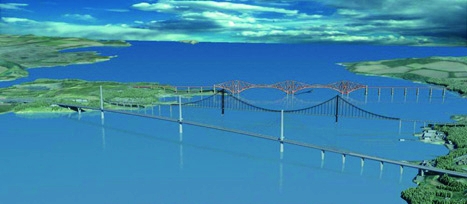
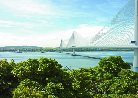
But within a few years, the view will be very different, with a third bridge adding to the vista. The Forth Replacement Crossing, for which works are now under way, will span the estuary to the west of the existing road crossing. It’ll look very different from the other two bridges: no curves, just the sharp lines and angles of a cable-stayed bridge, with supporting cables fanning down from three supporting towers in the middle of the water. The bridge will be more than twice as long as the older road crossing, at 2.65km.
Scheduled for completion in late 2016 at a cost currently estimated at around £1.6bn (considerably less than original estimations of some £4.75bn), the new bridge will take the traffic from the old suspension bridge, leaving it to pedestrians and cyclists. But this means that the original road crossing will have survived only 57 years – less than half the lifespan of its more famous rail-carrying neighbour.
’The problem is that the old road bridge was built in the 1960s, and at that time the understanding of the nature of corrosion was much less developed than it is now,’ said Steve Kite of Arup, one of the engineering companies involved in building the new bridge. In fact, the problems with the road bridge were only discovered in 2004 and came as a major shock.
Each of the two cables from which the roadway is suspended consists of 11,500 individual steel wires, each one about the width of a pencil, which were twisted together in situ as the bridge was built. Since the bridge was completed in 1965, the cables have been inspected regularly – but only on the outside. Following advice from US suspension bridge operators, the Forth Estuary Transport Authority (FETA) decided to commission the first internal inspection of the cables in 2003.
The results are detailed in a paper by Barry Colford of FETA and Charles Cocksedge of consulting engineering company Faber Maunsell. Several small sections of cable in different locations on the bridge were unwound and examined, with the expectation that there would be relatively little corrosion inside the cable – most of the wires were expected to be at stage two of the four recognised stages of corrosion. But when the first section was inspected, this was soon found to be wrong.
’It was to everyone’s surprise when broken wires were found at the bottom of the cable and examination of the cable surface showed many stage-four wires were present,’ said Colford and Cocksedge’s report. But this turned out not to be consistent along the cable’s length – in some locations, most of the wires were at stage two and none were broken; in others, more than 30 wires had snapped.
The difference is believed to be down to the direction in which the cable was originally twisted together – known as wrapping – during the construction of the bridge, much of which took place in heavy rain. If the wires were wrapped ’uphill’, any water present would have remained in the cable. Whereas if it was wrapped ’down-hill’, the water would have been squeezed out. Although the water would certainly have drained away over time, this original moist environment would have been a key factor in the faster-than-expected corrosion of the wires.
A suspension bridge would take six years to build, as it would have to be constructed in a strict linear sequence
However the water had got into the cable, the upshot was that the cable was clearly not as strong as it should have been and deteriorating at a rate much faster that anyone had expected. Studies on the progression of the corrosion showed that traffic restrictions would be required on the bridge as early as 2014 and no later than 2020.
The cables have now been protected by a dehumidifying system, consisting of a stretchy waterproof wrap and equipment to blow very dry air into the cable at low pressure. However, even though this could slow down or even halt the corrosion, the loss of strength in the cables is a direct result of the broken wires. Stopping the corrosion can’t restore lost strength, said Colford and Cocksedge. Corroded wires that contain cracks are still under stress and will eventually break.
’That link between Edinburgh and the north of Scotland is so vital to the Scottish economy that the government decided it couldn’t take the chance of it being cut or even reduced by having to bring in traffic restrictions,’ said Kite. ’So the decision was taken to go ahead and build a new crossing.’
Of course, there are several ways to cross an estuary and, even if a bridge is chosen as the option, there are many types of bridge. The reasons for opting for a cable-stayed bridge were outlined by Scottish finance secretary John Swinney in 2007.
Four options were considered: a suspension bridge, similar to the existing road crossing; a cable-stayed bridge; a bored tunnel (that is, excavated through the bedrock of the estuary); and an immersed tube tunnel, made from sections pre-fabricated on land and sunk to the bottom of the water.
A suspension bridge would take six years to build, as it would have to be constructed in a strict linear sequence – the cables have to be completed before the road can be built and hung off them. A bored tunnel would be technically difficult because of the geology of the Firth and could result in restrictions in the transport of flammable goods, such as whisky and oil – both of which are important constituents of the traffic on the crossing. Similar restrictions would apply to an immersed tube tunnel, and both tunnels would generate many thousands of tonnes of spoil. The immersed tunnel could also impose shipping restrictions on the Forth. The cable-stayed bridge option, carrying four lanes of traffic with hard shoulders, would be the cheapest and fastest option, because cable-stayed bridges are built outwards from their towers; work can therefore proceed at several places at the same time. It would impose no restrictions on traffic and would in fact be more reliable than the existing bridge, which does not have hard shoulders.
The decision was therefore taken to build a cable-stayed bridge, with Jacobs and Arup appointed as a joint-venture team to design, develop and manage the project in 2007. The watchwords for the design were ’elegant, unique and instantly recognisable’ – that distinctive landscape and engineering vista across the Forth would have to be preserved, and indeed enhanced, by the new addition to the infrastructure.
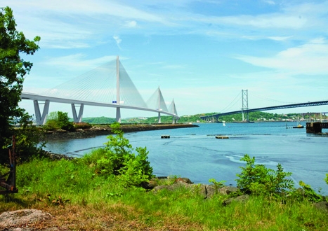
The triple-tower design is an unusual one for a cable-stayed bridge, according to Kite; they are more often single-tower or, at most, two-tower designs. But because of the length of the bridge, the extra reinforcement of a tower in the middle – actually sitting on an islet called Beamer Rock – was necessary. This means a particular challenge is to keep the bridge as stiff as possible along its length.
Cable-stayed bridges are, by their nature, stiffer than suspension bridges (see box), but at more than 2km in a windy location, the Forth replacement needs extra stiffness. Reconciling that with the desire for an elegant bridge is a tricky business. ’We want to keep the towers as slim as possible and not to visually dominate,’ Kite said. ’The challenge of getting that stiffness without adding visual mass in the towers or the deck has been very interesting.’
“The challenge of getting stiffness without adding visual mass has been interesting”STEVE KITE, ARUP
The key to the problem is the arrangement of the cables that support the roadway. ’We’re going to overlap the stay cables coming from different tower fans. That overlapping effect adds stiffness to the structure,’ Kite added.
Engineering consultancy Gifford is also working on the bridge, brought into the project because of the experience of its parent company, Danish engineering contractor Ramboll, on the Øresund and Great Belt Link cable-stayed bridges in Denmark. Peter Curran is part of the Gifford team, which is working on many aspects of the bridge design, from the foundations to the complex matter of supporting the bridge deck while it is being built.
As the main supporting structures of the bridge are the towers, rather than the cables, the bridge deck can be built outwards from the towers in both directions. This is particularly difficult because, although in the completed bridge the deck will be supported by two towers because of the overlapping cable fans, while it is being built a single tower will have to bear all of the weight. To get around this, while the deck is being built it will also be supported by tie-down cables from the bridge to the islet and by extra counterbalance weights to provide storm ballast.
Not all the cables in the bridge are the same. Their lengths vary from 94m to 420m and they contain between 40 and 104 strands of wire. Part of the specification procedure takes into account that the cables have to support the bridge during construction, Curran said; moreover, the designers have to ensure the anchorages don’t twist.
The political landscape in Scotland is probably more uncertain now than it has been for the last three centuries. If the Scottish National Party’s dearest wish comes true and Scots vote for independence in a 2014 referendum, then the new Forth Road Bridge could be the first landmark and symbol of a new nation; of course, the question could then arise of where the money to build it would come from.
But while the political landscape shifts, the physical landscape stays the same. The elegant, almost ephemeral lines of the new bridge should be a fitting part of the gateway to the Kingdom of Fife and to the capital of Scotland.
the data
forth crossing
The replacement bridge will feature no curves, just the sharp lines of a cable-stayed structure
- Length: 2.65km
- Maximum length of deck section: 32m
- Approach viaduct length: 500m
- Maximum span: 650m
- Height: 200m
- Number of stays: 288
- Stay length: 94-420m
in depth
staying power
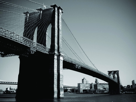
Examples of iconic cable-stayed structures include the Brooklyn Bridge in New York, built in the 1800sSuperficially, cable-stayed bridges resemble suspension bridges – in both, the road deck is supported by cables attached to a high tower or pylon. However, the two designs are very different. The difference lies in the way that the weight of the deck is supported. In a suspension bridge, the weight is supported by the two massive cables that run the length of the bridge and are attached at either end to anchorages in the ground or in some other heavy, stable structure. Rods or cables hang from the main cable and support the road, putting tension into the cables that are transferred into the ground. The force goes down the towers into their foundations and via tension into the cable anchorages at either end.
This imposes constraints on the way that the bridge must be built. The towers have to be completed, then the main cables installed, and finally the road deck is put into place.
In a cable-stayed bridge, by contrast, the weight is supported by the towers, with the cables transferring the load to the vertical structures and down into their foundations. This has both advantages and disadvantages. Unlike in a suspension bridge, the supporting cables are angled, not vertical; this means the bridge deck is under a certain amount of horizontal compression as the wires pull slightly into the towers; the deck therefore has to be stronger to cope with these forces. On the other hand, as all the weight is taken by the towers, the bridge does not need to be anchored at either end, and the forces on the towers are balanced so that the towers only have to cope with the ’live load’ of whatever is crossing the bridge. Thus the structure tends to be stiffer than a suspension bridge.
As each pair of cables on either side of the tower supports the section of road between the tower and the anchorage, the road can be constructed as soon as the tower is complete; and for a multi-tower bridge, construction is possible from all the towers in both directions. This means that cable-stayed bridges are often quicker to build than suspension bridges.
Cable-stayed bridges are, in fact, an old design: they are believed to have been invented in the late 16th century by Venetian engineer Fausto Veranzio, an intrepid man who also holds the honour of being the first parachutist. Several famous examples were built in the 19th century, including the Albert Bridge in London and the Brooklyn Bridge in New York. Recent examples include the UK’s second Severn Bridge and London’s Queen Elizabeth Bridge. The longest example, with a maximum span of 1,088m, is China’s Sutong Bridge, completed in 2008.


Swiss geoengineering start-up targets methane removal
No mention whatsoever about the effect of increased methane levels/iron chloride in the ocean on the pH and chemical properties of the ocean - are we...