From the brutal heat of the desert to the unforgiving ice of the Arctic Circle, engineers are venturing into increasingly harsh environments to recover oil and gas from marginal reserves. Much of these energy streams come in the form of ‘multiphase flows’. This is where liquid and gas are in the stream at the same time. It also describes liquids in which solid particles, such as sand and silt, are suspended.
Multiphase flows are becoming common with marginal hydrocarbons where engineers need to create mixtures capable of extracting oil and gas in low-pressure environments. Around 70 per cent of the world’s remaining oil reserves are believed to be in the high-viscosity, or ‘heavy’, category. Most are produced and transported as multiphase flows, usually as a mixture of gas, heavy oil and water. In some cases, multiphase flows are created when sand and chemicals are blasted into rock to free oil and gas.
According to NEL, an independent consultancy for onsite oil and gas measurement and evaluation, the components of a multiphase mixture can be difficult to track, because they travel at different speeds. “Generally speaking, the velocity of the gas is much greater than the velocity of the liquid,” said a spokesman. “In some production wells it takes the gas a few hours to reach the well head but it can take the liquid days to travel the same distance.”
”In some production wells it takes the gas a few hours to reach the well head but it can take the liquid days to travel the same distance
Multiphase flows can cause some significant problems for engineers. For instance, the flow can separate in the pipeline, leaving liquids behind. These liquids can then create backpressure problems. Meanwhile, temporary multiphase outflow changes can cause problems for the connected plant. Exactly how the material is distributed throughout the pipeline varies, based on velocities and orientation of the pipes, and the monitoring of it requires sophisticated tools.
To help overcome these problems, engineers often separate their flow early on in the process. “To be more realistic, water may be separated from a crude oil stream on offshore oil platforms rather than transported to the onshore facilities,” wrote Wuqiang Yang, in a paper for Manchester University. “Because the space on offshore oil platforms is limited and expensive, effective monitoring and control of the crude oil separation process on offshore oil platforms will result in huge savings to oil companies.”
In most production facilities, the first separation phase of any hydrocarbon production process usually begins once the product has started to flow from the well. Engineers must separate the gas from the liquids and the hydrocarbon liquids from the water. The same process takes place in marginal oil and gas production, such as when trying to extract shale gas. In this case, the hydrocarbon first needs to be separated from the flowback water using a series of sophisticated valves.
”Because the space on offshore oil platforms is limited and expensive, effective monitoring and control of the crude oil separation process on offshore oil platforms will result in huge savings to oil companies
Wuqiang Yang, Mamchester University
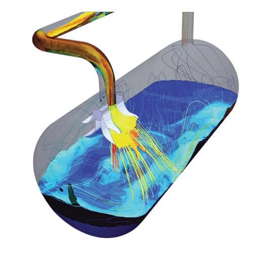
While the selection of separator is based on the specific flow mix, they largely work in the same way. The wellhead pipework sends through a mixture of oil, gas and water, which is controlled by the wellhead chock valve. The vessel then separates this mixture with the help of gravity. Oil floats on top of the water and gas forms above the oil. An extractor is often used to capture additional liquid from the gas.
A weir over the oil can flow into a separate chambers. The remaining water is drained from the bottom of the vessel.
This volumetric flow of most separators is controlled by the inlet valve position, which is often a wellhead choke valve. Meanwhile, outflows are regulated by control valves, and the pressure inside
the vessel is controlled by a gas outlet control valve. Some are simply on/off switches, while others provide a more continuous and smooth flow of oil and water from the separator allowing downstream production to be far smoother.
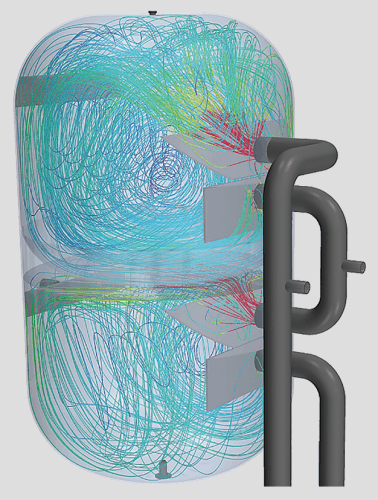
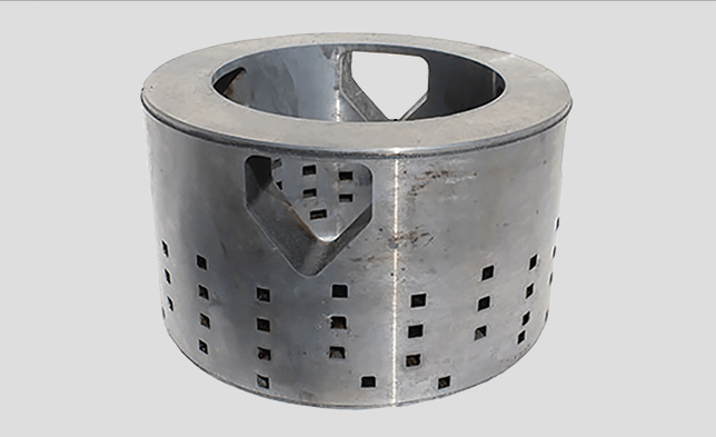
This technique is known as phase separation. An example is Cameron’s 3-Phase Separators – KCC Slug Catchers, NATCO Free Water Knock Outs and Multi-Phase Separators — which are typically fitted with effective inlet devices to absorb the momentum of the fluid. This removes gas that rises while the bulk liquid settles into the lower section of the separator through a valve that has horizontal flow.
Meanwhile, the heavier water phase settles by gravity beneath the lighter oil phase. “Liquid levels are maintained by weirs and actuated control valves,” said Cameron.
“Oil can be discharged from the separator through two or more compartments. With the addition of optional externally adjustable weirs, fluid levels can easily be adjusted as needed. Water is discharged from a single outlet located at the bottom of the vessel and gas is discharged through a separate outlet on the top of the vessel.”
GEA is offering to do the same thing with vertical bowl high-speed centrifuges. These are mainly designed to separate liquids with and without solids content. The maximum particle size that can be separated is 0.5mm with a total solids content of 0.1–3 per cent. “Only the high g-force of our separators can handle the low-density difference between, for example, heavy crude oil
and water in a reliable and efficient way,” said GEA.
IMI Critical Engineering, a provider of flow-control components, provides bespoke valves for such separators. It recently delivered a series of choke valves for the Tahiti facility in the Gulf of Mexico.
Choke valves control the rate of flow of liquids and gases. Each valve had to be able to handle multi-phase flow with entrained solids. “Two custom valve designs were provided; an 8in and 6in 11,000 API with solid tungsten carbide trim, capable of withstanding a 2,400 psi drop in pressure,” IMI explained.
As engineers venture to increasingly remote regions to find oil and gas, these systems are dealing with a greater variety of multiphase flows. Investing in the right separation technology now, could help save oil and gas operators money further down the line.
Red Bull makes hydrogen fuel cell play with AVL
Formula 1 is an anachronistic anomaly where its only cutting edge is in engine development. The rules prohibit any real innovation and there would be...