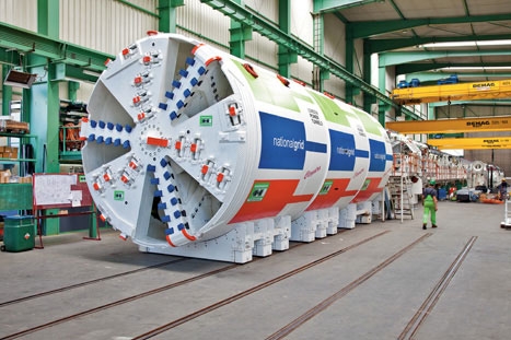
Deep beneath the busy streets of north London, one of the largest engineering projects that the capital has seen in the last 50 years has reached a major milestone. Last month at an underground site beneath Haringey, National Grid began assembling a 100m-long tunnel boring machine (TBM) - nicknamed ’Cleopatra’ by local school children - that will spend the next four years creating the passages that will carry London’s future electricity supply.
London currently accounts for 20 per cent of the UK’s electricity usage - a demand that is increasing by between three and five per cent every year. In order to supply the city’s substations with the necessary energy to keep up with demand, National Grid is constructing more than 30km of underground tunnels that will carry the 400,000V transmission line cables needed. One of the tunnels will also carry additional 132,000V cables to supply the distribution networks and so will need to be a metre wider.
’We’re replacing old assets and increasing capacity, making sure we’re looking at what the energy network is going to be doing in five, 10, 20 years’ time,’ said National Grid project manager David Luetchford . ’We’ll be getting more from the east coast [for example]. The energy flows will change across the whole country over the coming years with renewables, and that affects everything.’
The 3mand 4m-wide tunnels will connect substations in Wimbledon in the south, Hackney in the east and Willesden in the west with St John’s Wood, just north of central London. They will run underneath the Thames, Regent’s Park and some of the most densely populated residential areas - and most expensive real estate - in the country. National Grid hasn’t attempted a project of this size and complexity since installing the SuperGrid in the 1960s, but it has some compelling reasons for thinking big.
Instead of digging up and replacing the old cables that are buried under the roads - adding years of roadworks to London’s already chaotic transport network - the infrastructure company is creating an easily accessed space that will allow cable installation and maintenance to be carried out without any disruption to the public. It will also have room for additional cables that could be laid to meet future demand.
The tunnels will be deep enough that no noise or vibration will be heard or felt on the surface, meaning the crew will be able to work 24 hours a day, five days a week, to get the job done. Many London residents won’t know it’s going on at all, and those who live above the tunnels will only be aware of the work thanks to a substantial communication campaign by National Grid. But this has also meant major planning and surveying by the company and its main contractor, Costain, to navigate under - and occasionally over - London’s existing sub-surface infrastructure.
The depth of the tunnels will vary between 12m and 60m, said Luetchford. ’The shallower you are, the more clashes there are with other tunnels. We’re probably one of the deepest tunnels in London on average, because we go under the Underground in places but sometimes we go over. We’ve had to take the future position of Crossrail into account, and the future position of Tideway [the super sewer project] as it happens.’
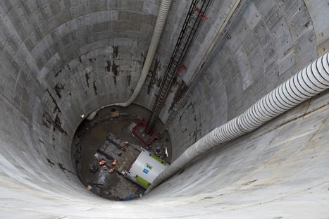
Before any work could start on the tunnels themselves, 12 shafts were needed along the route, 10 of which have been started and four finished. The 15m-wide shafts, which provide access and ventilation, are up to 4km apart and will create a route map for the TBMs. ’By having those shafts in place, we make sure we don’t tunnel any further than necessary,’ added Luetchford. ’You design a temporary ventilation system for the tunnelling operation where you force air down to a ventilation duct at the face so you have fresh air at the face and a draft coming all the way back.’
But a permanent system is also needed to keep the cables cool, and that adds to the substantial amount of planning permission and easements that need to be secured. ’You don’t need planning permission for what you’re doing underground, but you need it for the surface structures,’ said Luetchford. ’Each shaft has a head house with a fan arrangement in it and then you need planning permission for the substations themselves.’
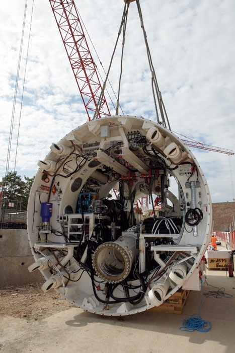
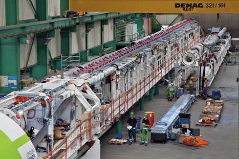
Getting a 100m-long tunnelling machine down the shafts would be quite a challenge, so the TBMs are put together underground, starting in a 60m-long concrete launch tunnel built by mechanical excavators. ’The machine comes in a series of bits, with a maximum length of 10m, and that process can take three to seven weeks,’ said Steve Meadowcroft, Costain’s tunnelling operations director.
Although building the machine is designed to be ’as close to plug and play as it can be’, the launch is the hardest part of the process, he said. ’The difficult thing with tunnelling is getting it going. Once you get the first 2km out the way, the rest of it follows from there. You’re establishing a cycle; you’re establishing methods; you’re getting the machine to work at its best. We have to launch the TBMs five times over the course of the project.’
The two machines are supplied by Caterpillar in Canada and Herrenknecht in Germany. Both operate at a speed of around 200mm/min, laying the concrete segments of the tunnel behind them as they go. Even though they can operate at between 300m and 400m a week, the team will likely take until at least 2014 to complete the tunnels.
But what makes modern tunnelling easier than with previous generations of TBMs is the electronic - rather than hydraulic - control systems. ’There are a lot more readouts that they can give you,’ said Meadowcroft. ’You can connect them directly via the internet back to the manufacturer, so if you have drive diagnostic issues you can speak to the manufacturer, which can look at the diagnostic as well. You get a greater degree of control and you can give the client greater feedback in terms of what the machine is doing.’
Information on the machines’ progress will likely prove especially useful thanks to the relatively soft clay soil found underneath London. In order to minimise any surface disruption or ’settlement’, the TBMs will use a process known as earth pressure balance (EPB), which involves putting pressure on the face of the tunnel behind an airlock in order to stabilise it.
Once the waste soil ’arisings’ have been passed down the TBM gantries and conveyed out of the tunnel, they will be put to a relatively unusual good use: sealing contaminated ground at former gas-holder sites in the city. ’We’re taking all of our soil - London clay, which is impervious so a good sealing agent - and using it in gas-holder sites around London that will be decommissioned over the coming years,’ said Luetchford. ’It cuts down the hauling distances so reduces the carbon footprint and it makes it into a useful material.’
None of this can happen quickly, however, and it will be 2016 before the first tunnel is energised and 2018 before the project is complete. But this is infrastructure built to last. ’The transmission network will always continue to develop,’ said Luetchford, ’but these particular assets will be in place at least for at least the next 50 years.’
Going underground
Earth pressure balance method has advantages over other machines
Earth pressure balance method has advantages over other machinesEarth pressure balance (EPB) tunnelling uses the soil excavated by the drill to create a support structure within the TBM’s front shield, unlike other machines that rely on a secondary support medium. The soil is loosened by a cutting wheel and falls through openings into an excavation chamber behind. A pressure bulkhead powered by thrust cylinders controls the soil and forces it into a state of equilibrium where it cannot be further compacted by the ground’s earth and water pressure. The excavated material is removed by an auger conveyor that delivers it to a further series of conveyor belts, which then load it onto the transportation gantries at the rear of the TBM.
The tunnels are then lined with steel-reinforced lining segments, positioned with erectors located behind the pressure bulkhead and temporarily bolted in place. Mortar is forced into the gap between the segments and the ground around them through injection openings in the machine’s rear shield or openings directly in the segments.


Nanogenerator consumes CO2 to generate electricity
Whoopee, they've solved how to keep a light on but not a lot else.