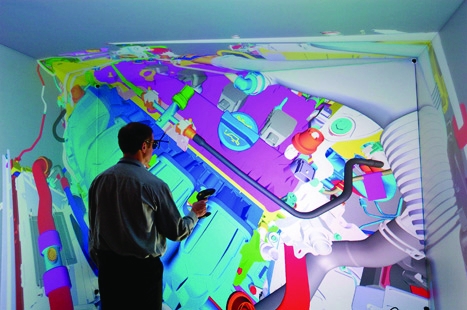
There’s a short slope in front of the 8ft- high projection screen housed inside the Warwick Manufacturing Group (WMG) building. It’s there to warn users of the 3D visualisation suite that they’re about to walk into the display, in case the immersive experience of three-dimensional life-size photorealistic graphics leads them to forget. From what The Engineer experienced when we visited WMG at Warwick University, it’s very much needed.

Watching computer simulations is no longer a case of staring at abstract shapes or 1990s-style video-game-quality images move around a monitor. Thanks to the development of hardware, software and processor power, designers can experience their creations with incredible realism, making changes that appear in real time.
WMG does this through means of a ‘powerwall’, a 5m and 4,000-pixel-wide back- projected screen that creates 3D images with four times the quality of HD video. Head-tracking software that follows markers on users’ 3D glasses allows them to effectively move around objects on the screen. And importing data from laser scans of real or prototype objects can add a whole other level of detail. ‘You can see the surface; you can see the lighting effects,’ said Prof Mark Williams, product evaluation technologies group leader at Warwick University. ‘You can change the reflection of the paint and see how that affects the style.’
As well as displaying finished or near-finished designs with such real-life accuracy, the powerwall can use computer-aided engineering (CAE) to show working simulations of systems. This means it can demonstrate exactly how a bullet penetrates body armour or the full effects of a car crash on every component. Allowing engineers to view their designs as large, comprehensive images can enable them to see things that they might not otherwise find out until much later in development — the movement of a particular part or a flaw in the simulation, for example.
The powerwall is able to display finished or near-fi nished designs with real-life accuracy
‘The end game of all these activities is to get products to market faster, to improve quality and also to save time and costly decisions and engineering changes,’ said Williams. ‘Visualising CAE data allows us to calibrate and really improve the accuracies of those CAE models. We can get more confidence in the data we can get more accurate simulation models faster and this has a huge impact on the product development process. But also, one of the major benefits of visualisation is the fact we can communicate results. A lot of simulation data is very technical; it’s quite difficult to communicate to non-CAE experts. We’ve held design reviews and had customers come in and really buy into those results and clearly understand what those results are telling them.’
WMG is now embarking on a project funded by the Technology Strategy Board to combine the photorealistic level of imaging with the CAE models. This will involve identifying all the hardware and software elements that then need to be combined into a single system without requiring so much processing power that it becomes uneconomical. ‘To get from the laser scanning of a component, characterising it, right through to the end product of visualisation, I reckon that’s a dozen pieces of software,’ said Williams. ‘The challenge of getting all those bits of software to seamlessly talk to each other, to have a process that a company can come in and use, is massive.’
A few miles from the university, Jaguar Land Rover (JLR) is taking a slightly different approach to immersive visualisation. At JLR’s headquarters near Gaydon, Warwickshire, engineers can get up close with their designs by entering ‘the Cave’, a special £2m room with powerwall-type screens comprising three of its walls and ceiling that’s big enough to fit a vehicle (or a dummy vehicle interior) inside.
‘Our traditional way [of interacting with the car’s physical properties] would be to build a physical model,’ said Brian Waterfield, JLR’s virtual-reality manager. ‘Now we have this virtual facility, we can take that to an early stage so we’re interacting with the vehicle, sitting in a physical seat and building a virtual car around us.’

Having already used the Cave to develop the Range Rover Evoque, JLR’s virtual-reality team is now developing its CAE capabilities. This will enable engineers to analyse how their designs perform in the real world, visualise the flow of air through the car or simulate how heat radiates through it. ‘This gives you that extra dimension,’ he added. ‘If you’re working on a desktop, you’re not able to see what the total effect will be… The Cave allows us to take a plane section through the vehicle and then look at it in more detail where the air flow is coming through.’
Like the Warwick team, JLR is working on bringing photorealism to its moving simulations, with some of the CAE options expected to be introduced by the end of the year, followed by more interactive elements in the form of haptic devices. Waterfield even hopes to be able to visualise the splashing of raindrops on the car.
Part of achieving all this will require a jump in processor power. Current CAE models in WMG’s system are already so complicated they have to be run overnight. ‘There’s a long way to go,’ said Williams. ‘But computer power is increasing readily, so the goal would be to run real-time simulations as we’re visualising them and then making design changes and seeing the impact of those changes in real time.’
Industry comment
Developments in simulation technology have opened the doors for design engineers says Tony Christian of Cambashi
As engineers have become very good at optimising the blend of performance characteristics for a vehicle’s target market, even on volume market cars, making even modest improvements from one generation to the next is a challenge and this makes simulation essential.
While the basics of simulation technology developing the model and applying constraints, the form of the equations and so on have remained the same, simulation technology has come a long way in terms of automating some of the processes, the presentation of results and, above all, usability. This has opened the doors for a new user: design engineers themselves.
Traditionally, the conceptual design geometry gets passed from the design engineer onto a specialist for simulation and analysis. The ensuing iterative process between the two parties is time consuming. Furthermore, the understandably different perspectives of designers and analysts hinder a holistic approach to the design process.
Advances in simulation technology are now offering the prospect of a fully integrated design process in which the simulation and analysis steps for all physical aspects are embedded seamlessly into the design engineer’s workflows.
The necessary integration capabilities, such as the geometry transfer between design and analysis systems, are already quite advanced.
The two main hurdles are usability and the computing power required, especially when combining multiple disciplines into multiphysics simulations.
In terms of usability, simulation technology now provides high levels of automation for the modelling process in areas such as mesh generation, validation, application of constraints and visualisation. Most computer-aided design (CAD) systems provide easy-to-use geometry transfer. All of this enables non-specialists to work with simulation tools, and we expect confidence in this approach to grow.
As regards computing power, there is no doubt that desktops and workstations typically used by designers and engineers are currently not up to the job.
One highly effective approach is to ‘beef up’ the workstation with a powerful but cost-effective graphics processor. NVIDIA’s Maximus technology is a leader in this area.
An alternative approach, advocated by Autodesk, is to exploit the ‘Cloud’ to access remote high-performance processors and ‘flex’ the power needed as required.
With the advances in integration and the now viable options of enhanced local processing or cloud-based processing, simulation technologies will soon become a routine design engineer’s tool.
Software case study
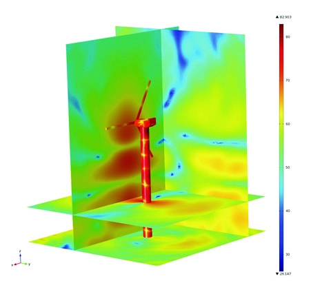
Multiphysics simulation software has helped a wind turbine manufacturer to eliminate excessive noise in its designs
When one wind turbine manufacturer found its designs were emitting excessive noise, the company called in Xi Engineering Consultants to solve the problem. After a thorough study of existing design data and an extensive site survey in which sensors were attached to the turbine towers, Xi confirmed that the source of the noise was the gearbox.
‘However, it was not that simple,’ said senior consultant Dr Brett Marmo. ‘The original noise was being amplified somehow and we suspected the involvement of the tower’s steel skin. Every structure has a harmonic and in this case the tubular steel tower had a series of resonances between 800Hz and 900Hz.’
To tackle this issue, Xi used COMSOL Multiphysics simulation software to develop a model of the tower, the rotor blades and the nacelle housing the gearbox. The model incorporated all of the air inside and outside the turbine so that engineers could identify the modal shape of each vibrating element and see exactly how vibration was travelling out of the gearbox.
This led them to the tower wall where resonances around 820Hz were clearly visible. The next step was to make a more complex model of the tower structure and skin. ‘Within this complex model, we could see that there were certain hotspots near the top of the tower where the tower skin was rippling at resonant frequencies of 800Hz and 830Hz,’ said Marmo. ‘These resonances were amplifying the gearbox vibration and producing the annoying tonal noise.’
The solution Xi suggested was to coat the inside of the tower with a specialist material that would reduce the amplitude of the vibration. The question was exactly how much material would be required to solve the noise problem. The only option was to create a third model to simulate the effects of the material inside the tower.
‘We made an acoustic structural interaction model of the tower walls and the internal and external air,’ said Marmo. ‘We determined what the sound level was 50m from the tower when different surfaces of the tower were covered in the material, rather like using a virtual microphone. As we adjusted the amount of material in the wall, we reached a point where the noise dropped to a satisfactory level. We continued to adjust the coverage until we had also minimised the amount of material required.’


April 1886: the Brunkebergs tunnel
First ever example of a ground source heat pump?