Dubbed “the world’s biggest eye on the sky,” the European Extremely Large Telescope (E-ELT), aims to help scientists find extrasolar planets that are orbiting other stars, answer fundamental questions regarding planet formation and better understand the nature and distribution of dark matter and dark energy. The E-ELT project was undertaken by the European Southern Observatory (ESO).
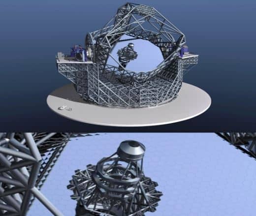
The E-ELT is a 39-metre main mirror, making it the world’s largest optical/near-infrared telescope. Because it is difficult to manufacture, deploy and maintain a 39-metre mirror, about 800 hexagonal mirror segments (Figure 1) with a 1.5 m diameter make up the mirror known as primary mirror M1. In comparison, the primary mirror of the Hubble Space Telescope has a 2.4 m diameter. To combat the image degradation caused by aberrations in the optical design and atmospheric interference, the E-ELT (Figure 2) employs an innovative system of active and adaptive optics for the M1 and M4 mirrors.
Using the LabVIEW Real-Time and LabVIEW FPGA modules with the PXI platform, engineers at Instituto de Astrofísica de Canarias met the real-time requirements and provided the flexibility needed for the actuator positioning system of the M1 mirrors. Using a COTS platform such as LabVIEW that allows for programming in real-time and FPGA-based systems, the domain experts at the ESO and Instituto de Astrofísica de Canarias developed a system that met stringent real-time requirements while keeping the development time down.
Active and Adaptive Optics
Active optics incorporate a control system and combination of sensors and actuators so that the telescope can maintain the correct mirror shape or collimation. The correct configuration for the telescope is actively maintained to reduce any residual aberrations in the optical design and increase efficiency and fault tolerance.
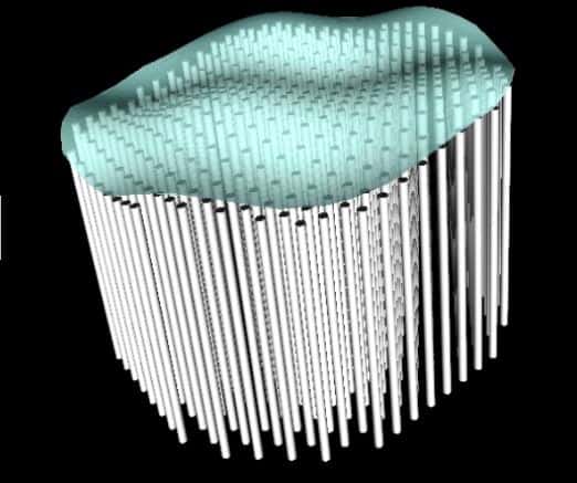
Adaptive optics monitor the effects of atmospheric interference at frequencies of hundreds of hertz and then corrects for them by physically deforming a suitably configured thin mirror (Figure 3) known as M4. Turbulence scale length determines the number of actuators on these deformable mirrors. The wave front sensors run fast to sample the atmosphere and transform any aberrations to mirror commands.
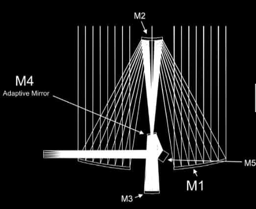
Both active and adaptive optics require fast software and hardware that are capable of interfacing with hundreds of edge sensors and servo controllers. Each mirror, shown in Figure 2, can be moved in real-time using three position actuators to compensate the deformations of the underlying support structure due to gravity, temperature and wind buffeting. The control of such a complex system requires an extreme amount of processing capability to manage the incoming data from the edge sensors, calculate the position and drive the actuators.
During the E-ELT project’s design phase, engineers from National Instruments collaborated with the ESO for the computation requirements of the control system of M1 and M4. Additionally, engineers at Instituto de Astrofísica de Canarias in Spain have worked on developing electronics and embedded software based on NI LabVIEW software and NI PXI platforms to manage and coordinate three nanometric position actuator prototypes. This article covers the control system’s high-performance computational requirements and the system developed to drive the position of the individual mirror segments.
Extreme Computational Requirements of the Control System
In the M1 operation, adjacent mirror segments may tilt with respect to the other segments. The deviation is monitored using edge sensors and actuator legs that can move the segment three degrees in any direction when needed. The 800-mirror segment comprises about 3,000 actuators and 6,000 sensors. The system must read the sensors to determine the mirror segment location and if the segments move use the actuators to realign them. The system software, based on LabVIEW, computes a 3,000 by 6,000 matrix by 6,000 vector product and must complete this computation 500 to 1,000 times per second to produce effective mirror adjustments.
Sensors and actuators also control the M4 adaptive mirror. However, M4 is a thin deformable mirror - 2.5 m in diameter and spread over 8,000 actuators (Figure 3). This problem is similar to the M1 active control; however, instead of retaining the shape, it is adapted based on measured wave front image data. The computational challenge of controlling M4 is about 15 times the computational requirements of M1.
The scale of this math and control problem required simulating the layout and designing the control matrix and control loop. At the heart of all these operations is a very large LabVIEW matrix-vector function that executes the bulk of the computation. M1 and M4 control requires enormous computational ability to compute the matrix vector multiplication, which was achieved with multiple commercial-off-the-shelf (COTS) multicore systems.
Because the complex control system could affect some of the construction characteristics of the telescope, it needed to be developed well before the actual E-ELT construction. To meet this challenge, engineers developed a system that runs a real-time simulation of the M1 mirror to perform a hardware-in-the-loop (HIL) control system test. HIL is a testing method commonly used in automotive and aerospace control design to validate a controller using an accurate, real-time system simulator. The control system and mirror simulation was also developed using LabVIEW and deployed to a multicore PC running the LabVIEW Real-Time Module for deterministic execution. The telescope simulator was then deployed to two readily available eight-core Dell workstations. The entire control loop was completed well below the loop time requirement of 1 ms to effectively control the mirrors.
Embedded System for Positioning Actuator
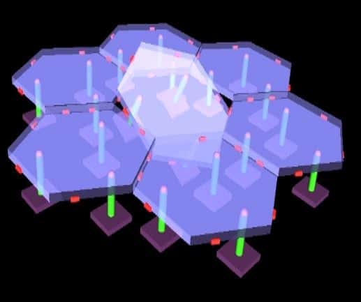
Each of the 800-mirror segments of the M1 mirror has three position actuators (Figure 4) and six edge sensors. The actuators’ most challenging requirements include a 15 mm stroke, support for a 90 Kg mass, 1.7 nm root mean square error (RMSE) following a slow ramp, 1 kHz external position command rate, and very low latency and jitter. The actuator mechanical proposal is a two-stage design. The coarse stage, with a brushless motor, gives a large stroke and coarse resolution. The fine stage, with a voice coil gives fine resolution, high bandwidth and small stroke. Each stage has its own power electronics, feedback sensor and servo controller. Fine and coarse stage controllers work in coordination to make the actuators work as a whole.
The electronics and software for the overall co-ordination, management of external commands, debugging functionality and implementation of servo controllers is based on a PXI system with a real-time OS. The servo controller of the fast fine stage is implemented on an FPGA-based PXI module, while the slow coarse stage controller is implemented on an embedded PXI-based controller (that is, a CPU). Additionally, the software design is divided into two applications: the actuator embedded software and a telescope simulator developed as an auxiliary tool to simulate the telescope computer that interfaces with the actuators.
Actuator Software
The real-time software includes the functionality of each actuator—initial shelf-checking, a state machine, a status word, an error register and the management of configurable parameters. Other tasks carried out include checking input coming from the FPGA card with serial peripheral interface (SPI) external commands, implementing the coarse stage servo controller to be transmitted through a controller area network (CAN) or CANopen to a brushless motor driver, managing a circular buffer for debugging purposes with synchronized data coming from a FIFO on the FPGA module, and reading feedback sensors through UDP/IP. The FPGA module implements the SPI slave, the fine stage servo controller, the analogue writing and reading, and the synchronisation to provide data to the real-time controller through a FIFO.
The Telescope Simulator
To test the position actuators against the requirements, a second application was developed for simulating the telescope computer that the actuators have to interface with through the SPI bus. This computer plays the role of SPI master while the actuators are SPI slaves. This auxiliary application sends millions of position commands through SPI at 1 kHz and reads SPI responses coming from actuators at 1 kHz. It also acquires digital data at 5 kHz from an additional external position sensor installed in the mechanical test bench to crosscheck with the actuator’s internal sensor. These three sources are required to register simultaneously with synchronisation greater than 200 µs, storing the data in binary files for offline analysis. This solution was also implemented using an FPGA-based NI card but installed on a PC running Windows OS.
Real-Time Performance and Flexibility
The actuator electronics and software have a wide variety of interfaces, most of which are open to changes during the first phases of the development including SPI, CAN bus, analogue input and output, digital input, TCP/IP and UDP/IP. Using all of these interfaces required a great amount of flexibility.
In addition, there were stringent real-time requirements such as reading the digital commands at 80 MHz and executing proportional integral derivative (PID) control of the fast fine stage servo controller between 2 KHz and 10 KHz. The system was also required in real time to synchronise and store large binary files for offline analysis of SPI external commands (1 kHz), voice coil current analogue acquisitions (2 kHz), position sensor data acquired through Ethernet (2–10 kHz) and servo controller internal variables (2–10 kHz).
By Arun Veeramani, Senior Technical Marketing Manager, Scientific Research & Lead User Program, National Instruments
For an overview of the products featured and to join the Developers community follow the links.
LabVIEW - http://www.ni.com/labview/
CompactRIO - http://www.ni.com/compactriodevguide/


Report highlights significant impact of manufacturing on UK economy
Note to Evil Villain/Dave 2020. Thatcher was PM for _11_ years, from 1979 to 1990 so no one under the age of 34 was even born when she left office....