The Engineer has followed Crossrail, the mammoth engineering project to connect London’s outer suburbs to the east and west of the city, running through Essex and Berkshire, by driving a new tunnel under the city to connect the mainline stations at Liverpool Street and Paddington, from the moments the enormous tunnel boring machines began chewing at the Earth, to where the eastern and western tunnels met. We have also looked forward to it successor project, Crossrail 2, which will travel from the north of the city to the south. The first project is now nearing completion, with its final stages – installing the linings, furniture and other fixings that will make up the stations themselves – well under way.
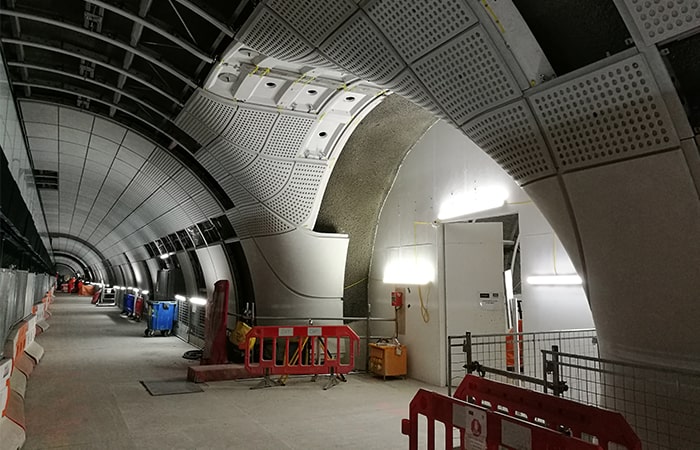
These are large engineering projects in their own right by any standards, although dwarfed by the magnitude of the entire project. Underground stations are complicated places, the equal of any major building, but with the added complication of being tunnelled out of the ground and having highly restricted access. Among the complicating factors is the geometry: instead of the regular orthogonal planes of normal buildings, these are structures made up from cylinders of different diameters which frequently join at odd angles, some of which will be occupied by many thousands of people throughout the day, others only accessible to the staff who will operate the station at normal times, and then areas only open to the dedicated maintenance staff who will take over the spaces for a few hours each night.
Each category of people have different needs and will occupy the spaces in different ways. Other parts of the station will have to contend with the regular vibration of trains arriving and departing, and of course, the spaces also have to accommodate electrical systems, with all their associated safety features, mostly tucked out of sight and safe behind panelling, while in addition, increasingly complicated audio-visual systems – including both advertising boards, which are nowadays electronic display screens, and passenger information equipment – will be threaded through the confined tunnels.
The complicated machinery of escalators, lifts, entry and exit gates and ticket machines also have to be accommodated. Moreover, this is railway infrastructure, which means that a modern advanced signalling system also has to be installed and tested. This confluence of interconnected demands has led to the opening of the Elizabeth Line being delayed by a year, from December 2018 to 2019, much to the annoyance of the travelling public.
The task of fitting out three of the largest and most complicated stations has gone to Bryden Wood, a multidisciplinary civil and structural engineering company originally set up in the mid-1990s to explore how the concepts of design for manufacture could be applied to this sector. Increasingly, this has seen the company becoming involved in off-site modular manufacture, constructing the elements of the buildings it works on – which have included schools and units for Gatwick airport – off-site in factories to a high level of finish, generally using the ‘flatpack’ philosophy, and then transporting them to the site to be assembled into a finished building. “It’s very much an attempt to improve the productivity of the construction sector, which is notably lower than that of the manufacturing industry and very dependent on specialised trades and their equipment arriving on site in sequence, which can often be disrupted by external factors such as traffic conditions and weather,” explained Jaimie Johnston, director and head of global systems.
Johnston is in charge of the project to fit out Liverpool Street, Whitechapel and Tottenham Court Road stations, which have the distinction of being some of the most complex on the line, tunnelled through areas with a high density of existing underground infrastructure which led to them having somewhat convoluted geometry. “One of the problems is that the tunnels we have to work in do not conform to very strict engineering tolerances,” he explained. “The tunnels were made by drilling through the ground and spraying a cement mixture on to the walls to stabilise them as they were excavated, and it isn’t possible to be completely accurate with that construction method.” Whereas in a conventional building the walls would be perfect to millimetre tolerances and the angles would all be nearly exactly as specified in the architect’s drawings, in the underground spaces of the Elizabeth Line, walls can waver along their designed route by a significant amount.
The consequence of this is that a standardised fixing system simply wouldn’t be practical. Moreover, the usual way of working on a construction site, where communication is via drawings issued to the site team, would also not be practical; it would require far too many drawings to cope with the complex 3D geometry. Johnston’s team, which was subcontracted by lead contractor Laing O’Rourke, therefore had to design a new system for making tunnel interior cladding that would be compliant with tight tolerances, but could still be installed into the awkward, non-compliant spaces left by the tunnel construction contractors.
The original design intent for the stations used a complicated steel fixing system that would be attached to the wall of the tunnel, and to which the panels that formed the cladding system would be attached. “This was highly complex, and the original design had cladding panels that were so heavy that they needed a complex superstructure behind them, and that required thousands of fixing bolts to attach it to the tunnel wall, which would have been expensive and complex to install,” Johnston said.
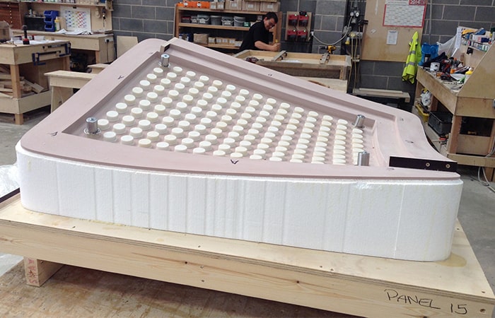
“Every junction between tunnels has different geometry, which precluded standardisation. We realised that the design intent was effectively just the inner face, so anything between that and the sprayed concrete wall was effectively up for grabs. We did finite element analysis (FEM) on the support structures, we did FEM, physical testing and bomb blast testing on the panels to see how thin we could get them, because that would mean we could strip down the support structure we would need.”
“We got the weight down by about two thirds, which reduced the parts count considerably. The concept we came up with, rather than fixing to the entire length of the surface of the tunnel, would fix to a single rail running along the wall that we would position with a laser line so it was precisely located in space, and do the same thing at the level of the platform itself, and indexed everything to those. That meant we could ignore the tunnel lining that was, in engineering terms, all over the place, and completely control the environment through those two fixed points which we created. That greatly reduced the number of fixing bolts we would need and allowed us to use a folding system to install a simplified fixing grid that unfolded between those two rails, and to which the cladding panels could be attached. As a result, the cladding installation is independent of the geometry of the sprayed concrete tunnels. It effectively meant we were working at zero tolerance.”
Known as ‘platforms’, this system is used in conjunction with point-cloud scans of the interior of the station tunnels, and has been developed in collaboration with Autodesk to work with Solidworks. It means that the GRP cladding panels themselves can be standardised for a straight or regularly curved tunnel, and only need to be custom-manufactured for the junctions between tunnels, with their complicated geometry. In these sections, known as ‘tasks’, the original design intent was for each cladding section to have its own frame, made from steel. Johnston’s team devised a way to make the support structure from GFRC as well as the cladding panel itself, greatly reducing weight and cost.
“One of the tests was that we had to be able to take panels off, so work could be done behind them, then replace the panels and readjust them within eight hours, which fits within the time available during the night shift for maintenance,” Johnston said. “We actually found that we eliminated adjustment time – you just clip them on and you’re finished. We got that eight hours down to 34 minutes. That all comes from eliminating any reliance on the tunnel geometry itself.”
It’s very likely that what we develop is working on Crossrail will come in useful for other types of project. In the Solidworks model, we literally have every nut, bolt, screw and washer in the digital to physical system, and that drives the whole assembly project. It’s likely we will use that approach in other modularised construction projects, because it is that which means we don’t need to use traditional drawings. We are almost finished on our original schedule for our three stations,” he added. “We expect that the size we mothballed until after the budget when it becomes clearer when they will open. Whatever is delaying the start of operations, it isn’t us.”


Nanogenerator consumes CO2 to generate electricity
Whoopee, they've solved how to keep a light on but not a lot else.