 Guest blog
Dan Slipper
Dan Slipper of Horiba MIRA discusses some of the significant opportunities that the use of Model Based Systems Engineering (specifically SysML) presents to the automotive industry. He demonstrates how it can support concept phase specification and system analysis and summarises the experiences that engineers at Horiba MIRA have had throughout its adoption.
Developments of modern vehicles are increasing in complexity at a rapid rate. With the advent of hybrid vehicles and X-By-Wire technology, the tasks which were typically performed by other technologies are now being performed by electronic and electrical systems. Not only are the technologies changing, the timescales in which such projects are expected to be delivered are often highly constrained, with the same expectations of quality, reliability, safety and security.
Standards such as ISO 26262 [1] (Automotive Functional Safety) and ISO 15288 [2] (Systems and Software Lifecycle Processes) are in place to include rigour in the process of system development and both propose a V-Model style lifecycle. These processes support a “left-shift” in engineering effort putting emphasis in understanding the system well during the requirements elicitation and analysis phases of the lifecycle, aiming for a “right first time” approach. This offers a benefit to OEMs as the cost to extract defects increases significantly through the later phases.
The use of semi-formal notations, such as the Unified Modeling Language (UML), are common practice in software development and highly recommended by the software part of ISO 26262. A proposed addition in the upcoming revision two of this standard is the recommendation that such formal notations should be used for specification at the system level, rather than just software.
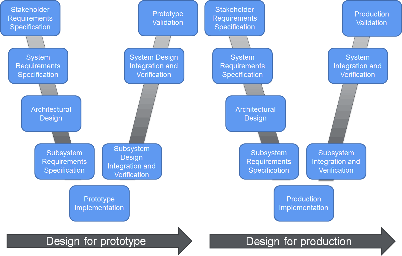
One approach which helps ensure the system is well understood at the concept phase is to use a “Dual-V” model (see Figure 1), the first half of which is a “design for prototype phase” used to gather requirements, develop a concept and verify the design meets the requirements. Stakeholders can then assess the design to verify that it meets their requirements and that the system being designed is right for its purpose. Once this has been performed the project can enter a “design for production phase”, where the design is realised. This blog focusses on the “prototype phase” of this lifecycle.
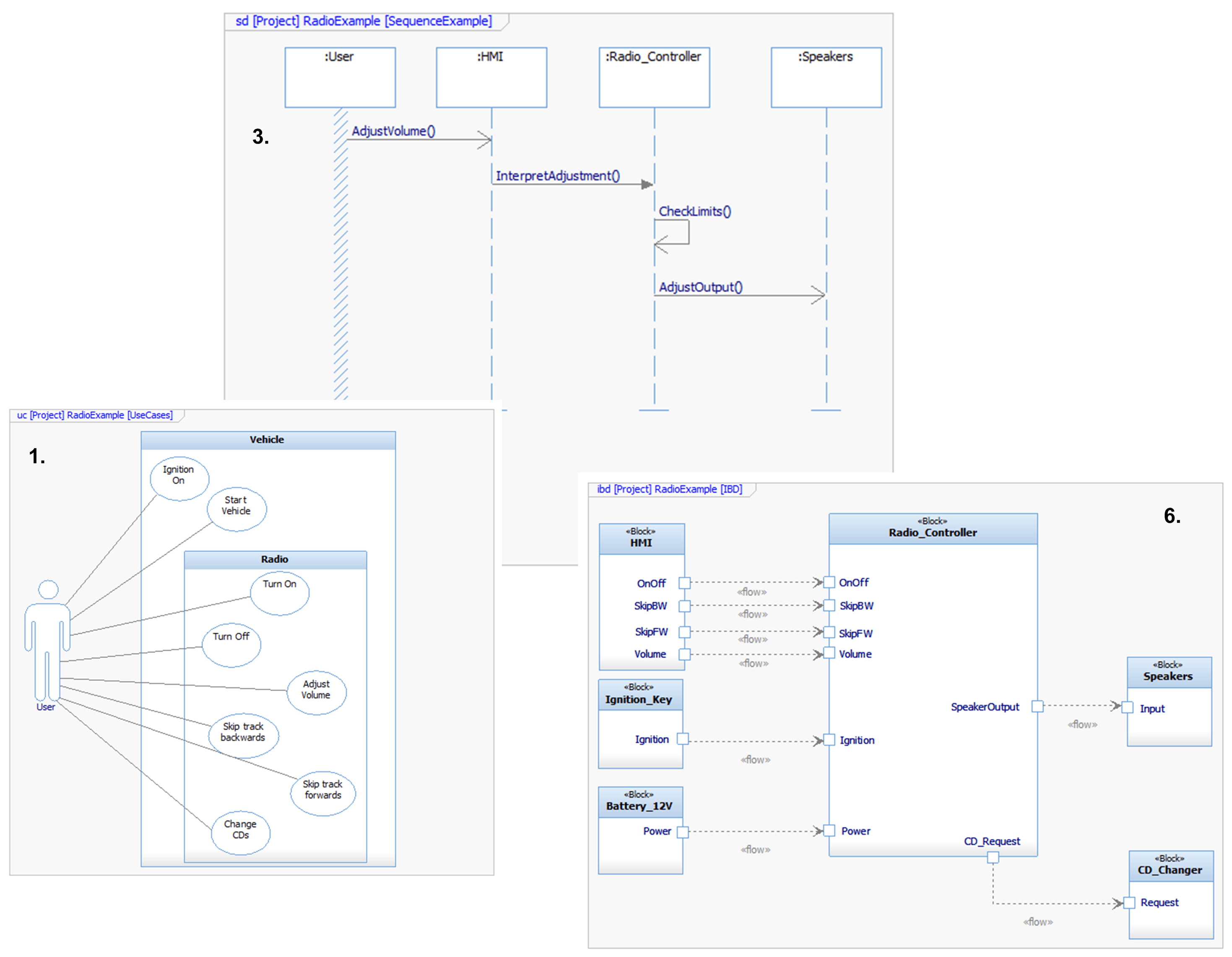
In general terms, a model is an abstraction of reality and may be capable of providing different “views” of a system. The Systems Modeling Language (SysML) [3] is of particular interest in this blog. It is a notation through which it is possible to model the behaviour and structure of a system by:
- Capturing stakeholder needs in use case diagrams to model how each of the actors interact with the system
- Linking requirements to use cases to demonstrate traceability using requirements diagrams (or by linking to a requirements management tool)
- Specifying the sequence of communication between actors and architectural elements of a system using sequence diagrams
- Describing either transitions between operating modes of the vehicle or state changes within the system using state machine diagrams
- Specify the behaviour in terms of flows and control using activity diagrams
- Defining the structure of and interfaces between elements (or subsystems) using internal block diagrams
- Defining block types and relationships using block definition diagrams
- Modelling mathematical relationships and constraints using parametric diagrams
Rather than producing standalone documents or diagrams, a model based approach uses multiple viewpoints to present the relevant information to different stakeholders, whilst still maintaining the underlying model. Where changes are made to one view, any impacts will be visible in other views and provide consistency across the system. This has been particularly useful in modelling the system architecture of the follow-up to the Hybrid Integrated Urban Commercial Vehicle (HiUCV) project that HORIBA MIRA recently contributed towards, where work was split across a consortium of companies who had different stakes and interests in the project. A further benefit is that queries and analysis can be performed upon a model to generate metrics against the different links in the model, which support tracking and reporting of project progress. For example, in terms of implemented, tested and satisfied requirements.
Modelling has advantages over a textual based document as it forces the concepts to be represented logically (e.g. using approaches such as activity diagrams and state machines), which helps clarify the needs of stakeholders with a logical and visual representation of the desired system. It also becomes clear when alternative conditions have not been considered (i.e. the behaviour given success of failure of a decision may not be apparent from a textual description). This gives the benefit to OEMs that the nominal behaviour and response to faults are considered upfront, reducing the risks of potential rework during the testing phases of the lifecycle.
As with any application of systems engineering to a project, to achieve a successful application of MBSE it requires a full commitment to the approach – results are best realised when implemented by a team of competent people, following a defined process and with training to use a suitable tool. HORIBA MIRA, in partnership with MBSE Training and Consulting Ltd, offers an introductory training course in this area.
Documentation of the requirements, decisions, architecture and testing of a system is key to communication to the members of a team. By working on a common model it is possible to see all changes that are being made by other members of the team. Different disciplines can also work from a common, consistent and complete model for analysis in the areas of safety, cybersecurity, reliability, etc.
In summary, SysML is just one notation that can be used to achieve a MBSE approach. One of its major benefits is that it provides constructs which allow OEMs to perform early verification that requirements are allocated to (and fulfilled by) elements of a system design, they can define how sub-systems will interface with each other in a semi-formal manner and this can be used for communication with suppliers to model the behaviour and interaction of any components.
References
[1] ISO, ISO 26262 - Road vehicles — Functional safety, 2011.
[2] ISO/IEC/IEEE, ISO/IEC/IEEE 15288 - Systems and software engineering -- System life cycle processes, 2015.
[3] Object Management Group, "SysML Open Source Specification Project," [Online]


Red Bull makes hydrogen fuel cell play with AVL
Formula 1 is an anachronistic anomaly where its only cutting edge is in engine development. The rules prohibit any real innovation and there would be...