
The Aircraft Carrier Alliance’s Goliath crane at Rosyth dockyard has had a busy couple of months at the start of this year. It seems that HMS Queen Elizabeth gains new structures on an almost weekly basis.
The first Rolls Royce MT 30 marine gas turbine, weighing 120 tonnes, has been lifted into position on the forward starboard sponson and then enclosed by the upper sponson unit. The two MT 30 gas turbines and their alternators are the heart of the aircraft carrier, each producing 35 MW of electrical power at 11,000 volts. This powers the propulsion motors and, after being transformed to 440V and other low voltages, the ship’s hotel and mission systems.
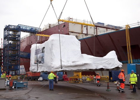
The MT 30s are high power density machines and their location in the sponsons high in the ships provide for short intake and exhaust ducting up into the islands (the structures that sit above the flight deck) and straightforward removal routes through the hangar for maintenance. The aft starboard sponson is being prepared for installation of the second MT 30 within the next few weeks.
In early February the upper section of the bow was installed. This block, containing the forward mooring and anchoring equipment, completed the flight deck at the forward end and gives the ship the characteristic look of an aircraft carrier, although it is perhaps not the most aesthetically appealing part of the ship.
Meanwhile further aft, progress has been made on the centre blocks enclosing the hangar on block 4 and extending the flight deck aft. The first two sub-blocks CB04a and CB04b have been installed, while the remaining two CB04c and CB04d have been delivered from Cammell Laird at Birkenhead in a very high standard of completion; even the compartment lighting is operational!
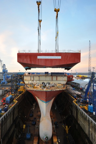
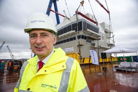
A major milestone for the programme was achieved on 14 March when the 700-tonne forward island, complete with already installed bridge equipment and windows, was lifted into position on the starboard sponson and carefully aligned with the gas turbine intakes and exhausts. The milestone was marked by the serving of bacon butties to all the workforce at Rosyth, and the ceremonial cutting and eating of a forward island shaped cake at the offices in Bristol. The Secretary of State for Defence, Philip Hammond, visited Rosyth to address the workforce on the flightdeck and then set in motion the procedure for lowering the island the last few metres on to the deck.
The lift of the island structure was probably the most complex of the lifts that have so far been undertaken. Its complex shape required us to manufacture a lifting frame which the island structure sits in, and the rigging of the lifting wires and associated spreader bars was quite a challenge. It was particularly important that the centre of gravity was accurately calculated as some of the rigging was very close to the overhanging structure on the island. With a great deal of careful preparation the lift was very well executed and carried out without a hitch.
Down in the dry dock at the aft end the huge A shaped brackets that will support the propeller shafting have been lifted into supporting frame works in the dock as have the rudder assemblies. Then the two parts of Lower Block 05 rings T and U have been lifted into position aligning with the A brackets and rudders. The installation of ring U on March the 20th was at over 900 tonnes the heaviest lift on the whole ship and means that the complete length of the ship is now visible in the dock. As these blocks are structurally consolidated we are starting to turn our attention to the installation of the propeller shafts and the brake propeller blades that will allow us to run the propulsion system at up to 50% power when afloat in the basin.
Away from Rosyth, the Integrated Platform Management System (IPMS) team has worked very hard to complete the Factory Acceptance Testing of the second release of software at the shore integration facility at Aztec West in Bristol. This release will shortly be installed on the ship’s hardware and allow the commissioning teams to continue to set the low voltage electrical systems working.
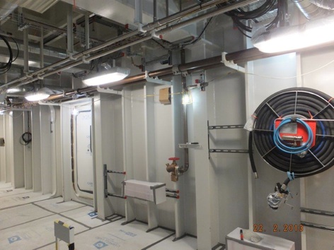
The ship has a single Integrated Network Environment (INE) to distribute data, both in support of the Mission Systems and also the IPMS. This novel approach replaces the multiple networks that would traditionally have been fitted and is key to the successful operation of the ship’s software systems. The INE comprises a network of thin plastic tubing (micro duct) along which optical fibres are installed by blowing them along the tubing using compressed air, and a large number of network switches that provide the intelligence to the network. Installation and setting to work of the INE is one of the key risks that we are carefully monitoring, as so much of the aircraft carrier’s capability relies upon it. It was thus extremely pleasing that the Factory Acceptance Test of the INE was successfully completed in February and as the installation of the micro ducting on the ship is progressing. We are looking forward to blowing the first fibres in the future.
Fabrication of the pole mast has recently been completed in Portsmouth. This mast incorporates a number of sensors and when fitted to the aft island will be the tallest part of the aircraft carrier. So tall, in fact, that it will have to be lowered for the ship to pass under the Forth bridges. In order to achieve that an hydraulic system is incorporated that can lower and raise the mast in minutes. Also to be fitted to the aft island is the Artisan Medium Range Radar (MRR) which is being manufactured by BAE Systems in Cowes on the Isle of Wight. On a recent visit to Cowes I was able to see HMS Queen Elizabeth’s MRR undergoing factory testing and the roll and pitch interface unit that takes ship roll and pitch data from the ship’s navigation system and provides input to stabilise the radar beam being tested. Subsequently I have seen a video of the radar being tested with the roll and pitch interface unit in a simulated very rough sea situation. Watching the radar gyrating to keep the beam steady while the ship moves around is enough to make you feel quite sea sick!
Everyday our ship looks more and more like the finished article, and with the systems starting to come together and the crew starting to join, the ship is really starting to come to life.


Red Bull makes hydrogen fuel cell play with AVL
Surely EVs are the best solution for motor sports and for weight / performance dispense with the battery altogether by introducing paired conductors...