Mahindra Two Wheelers used multiphysics simulation to meet engine noise regulatory requirements in its high-end luxury motorcycles while maintaining customers’ satisfaction.
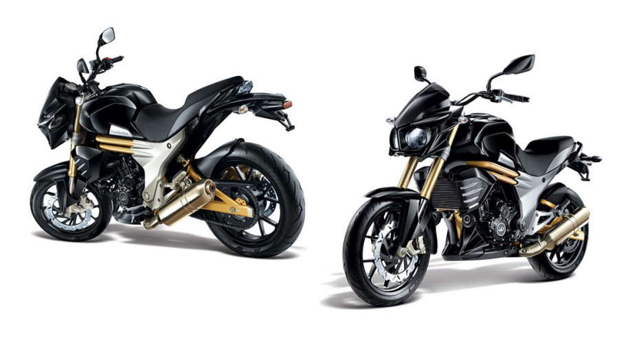
Mahindra Two Wheelers builds a wide range of scooters and motorcycles for the Indian market. Thanks to the adoption of numerical simulation tools early in the development cycle, drivers and passengers can enjoy great performance and mileage, along with a superior ride experience on tough Indian roads. Mahindra used multiphysics simulation to study the NVH (noise, vibration, and harshness) performance of the engine, intake and exhaust systems of their motorcycles.
The knowledge gained from numerical simulation studies enabled their engineers to improve the structural design of their motorcycle engine and achieve desired noise levels. “COMSOL software helped us to significantly reduce the number of design iterations that we had to go through, thereby saving time,” said Niket Bhatia, deputy manager R&D, Mahindra.
Achieving Optimal Noise Levels
In an engine, there are many sources of noise, including the intake and combustion processes, pistons, gears, valve train and exhaust systems. Combustion noise is due to structural vibrations caused by a rapid pressure rise within the cylinders. These vibrations continue from the powertrain to the engine casings through bearings, radiating noise.
Acoustics analysis solely through physical testing can be an expensive and time-consuming process. The team at Mahindra decided to complement physical testing with acoustics modelling to analyse how the engine’s structure might encourage noise radiation. The research goal was to find the parts of the engine that generate the most noise and come up with changes to the structure that could reduce it.
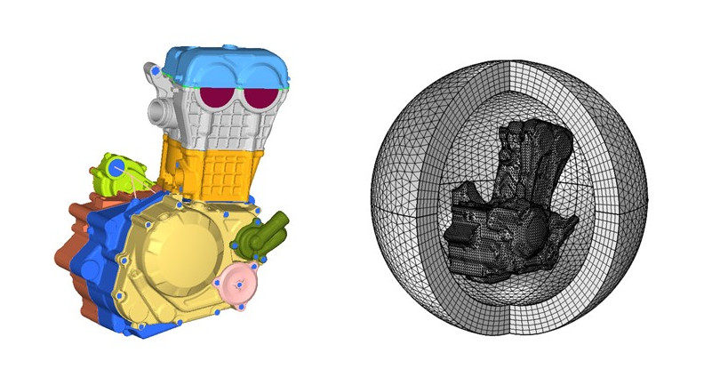
Using the COMSOL Multiphysics® software, the researchers performed an acoustic-radiation analysis of a single-cylinder internal combustion (IC) engine under combustion load. The engineers enclosed the engine skin in a computational domain surrounded by a perfectly matched layer (PML). PML's dampens the outgoing waves with little or no reflections (Figure 1). This allows for accurate results while reducing the size of the computational domain.
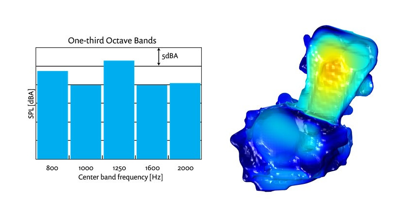
The team decided to focus their analysis in the 800 Hz -2000 Hz frequency range, as physical experiments indicated that the motorcycle's engine noise radiation under combustion load was dominant in that region of the acoustic spectrum. This choice allowed the team to save computational resources and better understand what areas radiate the most noise.
Based on this analysis, the sound pressure level (SPL) was studied and modifications, such as increasing rib height and wall thickness and strengthening the mounting location, were made to the cylinder head and block (Figure 2). By adjusting these parameters, reduction in SPL was achieved at the targeted frequency range.
Reducing Intake Structural Noise
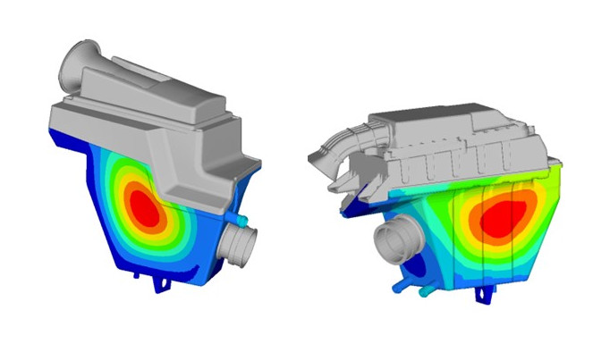
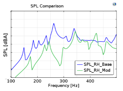
Both intake and exhaust noise are major contributors to pass-by-noise. Noise radiating from the air filter structure, usually made of plastic, is one of the major contributors to intake noise. An acoustic transfer function (ATF) analysis was carried out for the plastic air filter walls. The air filter structure was modified by providing ribs to improve the ATF (Figure 3). This helped in reducing the structural noise of the air filter (Figure 4).
Analysing Transmission Loss to Improve Muffler Sound
Regulatory requirements are always competing with customer demands for louder ‘rumbling’ from the muffler, as it is perceived as an important indicator of the motorcycle’s power. Within the constraint of pass-by-noise, the challenge for Mahindra engineers was to increase the ‘rumble’ sound from their muffler at low frequencies while reducing the sound level for higher frequencies.
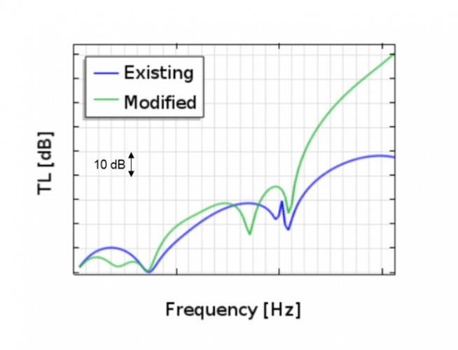
While attenuation of engine exhaust noise is the primary function of the muffler, factors such as the ability to provide low back pressure and meet pass-by-noise regulations also need to be considered. The performance of a muffler in an automotive exhaust system is characterised by three parameters: transmission loss, insertion loss and radiated noise levels. Transmission loss is considered the most important parameter and it is determined solely by the muffler design and is independent of the pressure source. The challenge for the team at Mahindra was to predict the transmission loss for a motorcycle muffler and then optimise the loss to desired levels for a certain frequency range.
A muffler of a single cylinder motorcycle engine was considered for the analysis. Transmission loss analysis of the muffler was carried out using COMSOL Multiphysics. With the Acoustics Module, boundary conditions such as continuity and sound hard wall were applied at appropriate locations.
Perforations in pipes were defined by giving porosity details for the perforated area using a built-in transfer impedance model. The inputs required for analysis were the area porosity, baffle and pipe thickness and diameter of holes. For porous materials such as glass wool, flow resistivity was defined with a poroacoustic model available in the software. Unit pressure was given as input at the inlet and a plane wave radiation condition was applied to both inlet and outlet boundaries.
Based on the results, the muffler design was modified by increasing the pipe length inside the muffler. With the modified muffler, the team achieved reduced transmission loss at low frequencies (Figure 5). As a result, the desired outcome of increased noise levels at low frequencies, or the ‘rumbling’ noise, was achieved.
Optimisation Early in the Design Cycle Leads to Cost and Time Savings
“I personally really liked the software’s flexibility and available tools like the COMSOL API,” said Ulhas Mohite, manager of R&D, Mahindra. “It allowed us to carry out process automation using Java code which, while dealing with acoustic analysis for example, enabled us to use different meshes for different frequency steps to find the right compromise between simulation accuracy and computational time. It also enabled us to automatically export desired outputs such as surface SPL plots and far-field SPL data in the middle of the simulation run. This helped save a lot of time with respect to manual postprocessing and exporting the data.”
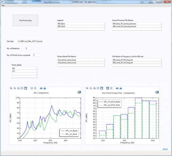
Mohite also found the Application Builder tool available in COMSOL extremely useful. “We created a simulation app (Figure 6) using the Application Builder to compare analysis output files and plot the SPL data, which was a great time saver.”
Analysis results proved to be very closely correlated with physical experiment data. With simulation, the engineers at Mahindra were able to take corrective actions by carrying out structural modifications based on analysis results early in the design stage. This helped reduce both time and cost involved in product development. “When supported with experiments, these simulations lead us in the right direction to find an efficient solution to motorcycle noise issues,” concluded Bhatia.


April 1886: the Brunkebergs tunnel
First ever example of a ground source heat pump?