
Their forms are mathematics made solid, their supports, curves and towers showing, often in a striped-down form, exactly how the forces that allow vehicles and people to cross them are distributed through their structures. And, often, they have stories: of challenges overcome; of ingenuity; and of triumph and sometimes tragedy.
There isn’t space for an exhaustive study of bridges and their place in civil engineering; such a thing could fill many volumes. This article will confine itself to some highlights and milestones in bridge technology.
Britain’s history with bridges goes back millennia. London, for example, owes its existence to the bridge technology available the Romans; the city grew up around the lowest bridging point of the River Thames when the Emperor Claudius’s invasion forces established their encampments in 44AD.
Onward through the centuries, the development of new materials and methods or working with them drove bridge design, with notable examples including the world’s first arch bridge made from cast iron, crossing the River Severn near Telford in Shropshire, which opened in 1781. Now an icon of the industrial revolution and a World Heritage Site, the Iron Bridge was designed by architect Thomas Farnolls Pritchard and includes design elements of stone and wooden bridges.
When the Engineer was first launched, in 1856, the state of the art in bridge technology was the suspension bridge, and one of the most famous examples of the design was in gestation. The City of Bristol had decided that the gorge formed by the river Avon in Clifton, in the west of the city, needed to be spanned, and had initiated a competition to select a design. Victorian Britain’s best-known engineer, Isambard Kingdon Brunel, submitted four entries, but the competition collapsed after none of the designs were thought feasible. Another design, by the chief judge, another eminent Victorian engineer, Thomas Telford, could not be funded.
In a second competition in 1831, Brunel was declared the winner after a private meeting with one of the judges. The span required for the bridge, a little over 214m, was so wide that even Brunel’s father, civil engineer Marc Isambard Brunel (best known for the first Thames tunnel), thought it couldn’t be crossed with a conventional suspension bridge; he advised his son that a central support would be needed, although the younger Brunel ignored him.
One reason for this may have been that Brunel had been granted permission to use a technology that had been patented by Sarah Guppy, a Bristolian woman whose eldest son had worked on the Great Western Railway and become friendly with Brunel. Guppy patented a method for making safe pilings for bridge towers in 1811, which were particularly useful in sites where the foundations of the towers were in danger of being washed away. Guppy had already granted Telford permission to use this technology on his Menai Supension bridge linking Anglesey to the Welsh mainland in 1826, and did Brunel the same favour. By contemporary account a shy woman who put great store by modesty, Guppy’s contribution to the UK’s bridges is still little-known.
The Clifton Bridge is an early example of recycling in engineering. The chains that support the bridge deck (which, to the surprise of many, is made of wood, reinforced with asphalt) were those from one of Brunel’s earlier bridges, the Hungerford footbridge in London, which had been dismantled to make way for a new railway bridge into Charing Cross Station. The triple chains - specified by a revised design to strengthen the structure which was devised by William Barlow and Sir John Hawkshaw, were of wrought iron; lower in carbon content and stronger than cast-iron and more readily available than steel, which at that time was not yet made in sufficient quantities to be cost-effective. The chains are anchored in blocks of brickwork secured at the end of 25m-long tunnels at either end of the bridge, and the deck itself hung from vertical suspension rods. The bridge was completed in 1864, and opened in the same year.
By the 1880s steel had become more readily available and was the material of choice for anther iconic bridge, the Forth rail bridge in Scotland. A cantilever bridge whose construction uses beams projecting horizontally but secured only at one end to support central bridge modules and carry the stresses of the structure and trains passing along it into granite piers on the bed of the River Forth, it was designed by railway engineers John Fowler and Benjamin Baker to replace an earlier design by Thomas Bouch, which was abandoned after his Tay Bridge collapsed in 1879.
The Forth Bridge has a near-twin across the Atlantic in Quebec with an ill-starred history. Built some years later than the Forth, the Quebec Bride (which consists of one double-cantilever, rather than the Forth’s three) collapsed twice during its construction. The first time, in 1907, resulted from mistakes made during the design calculations that meant that the weight of the bridge was far in excess of its carrying capacity. The construction teams were warned of this, but the warnings only reached the site after the bridge had collapsed, killing of 75 of the 86 workers on site at the time.
A team including Maurice FitzMaurice, an engineer who had worked on the Forth Bridge, drafted a different and more massive design. Construction restarted, but in September 1916, a problem with lifting equipment caused a failure as the central section (between the two cantilever diamonds) was being moved into place, and it fell into the Quebec River, killing 13 workers. The fallen section is still on the river-bed. The bride was finally competed in 1917, and with a central span of 549m, remains the longest cantilever bridge span in the world.
The next major advance in bridge technology is also in the Americas, and is one of the world’s iconic engineering structures. The Brooklyn Bridge in New York City, connecting Manhattan Island to the Outer Boroughs, embodies several innovations, probably the most of important of which are in its cables.
Although the Brooklyn Bridge resembles a suspension bridge, it isn’t one – it’s a hybrid. Between its two towers, the deck is supported like a suspension bridge, but on the landward side of the towers, the cables form the distinctive fan-shape of the bridges that now dominate construction, the cable-stayed bridge. This means that there was no need for the cables to be anchored some distance away on the landward side to carry the stresses into the ground, like on the Clifton Bridge.
The main engineering figures on the Brooklyn project were John Augustus Roebling, a German immigrant and steel maker, who had previously designed other suspension bridges in the US, and his family. Before emigrating to the US, Roebling had become interested in rope-making, because he believed that the ropes that had been used to tow barges could be improved. He developed a method for making a rope from seven strands of steel wire, and later refined this into a system to spin the ropes into cables in situ during the bridge construction itself. Cables had been demonstrated as superior to chains for suspension bridges as early as 1830, but the technology had not at that point been available to make them.
Roebling’s technique starts by stringing a ‘pilot line’ between the highest points of the support towers. A large spool of wire is placed at one end, and anchored in place. The free end is looped around a spinning wheel on the pilot line, and is sent to the other end, where it is again anchored (components called ‘strand shoes’ are used for this; they are basically eye-bolts attached to a steel channel). This is continued until the desired thickness of cable is reached, which can be 125 up to 400 wires. Extra cables are added to make the entire structure, which is then compacted into a cylindrical shape using radial jacks and the whole structure wrapped in more steel wire. Roebling also designed a steel reinforcing system to prevent the deck of the bridge twisting.
Spinning the cables for the Brooklyn Bridge began in 1877, under the direction of Roebling’s son, Washington. In an early example of the bad luck that would dog the family’s involvement in the project, Roebling senior’s foot had been crushed between a ferry and a piling while he was surveying the bridge site, and he died of tetanus contracted as a result of his injuries less than month after the accident.
Misfortune was also to strike Washington. The bridge supporting towers were built using caissons – upside-down cylinders that were placed on the river bed, inside which workers would excavate to sink the structure into the bed and form the foundations for the tower. Because of the water depth, the air inside the caissons had to be pressurised, and emerging from this pressurised environment was hazardous. Washington directed effort to fight a fire inside a caisson (safety was poor; dynamite was used in the confined space) and, like many other bridge workers, he contracted decompression sickness, where nitrogen forced into solution in the blood in a high-pressure environment returns to its gaseous state as pressure is relieved, causing injuries particularly to joints and lungs. Today known as ‘the bends’ and mainly affecting scuba divers, in the 19th century it was known as Caisson Disease; it also affected many workers on the Forth Bridge.
It left Washington paralysed and unable to supervise work in person, so his wife, the remarkable Emily Warren Roebling, learned higher mathematics, bridge construction and cable fabrication and acted as day-to-day supervisor and project manager, although Washington remained formally chief engineer (Emily was the first person to cross the bridge when it opened in 1883). The Roebling family’s unlucky relationship with engineering icons continued into the next generation; Washington’s nephew was killed on the Titanic.
With its 486m span 50 per cent longer than any other bridge when it was completed, Brooklyn remained the longest in the world for decades. Longer suspension bridges succeeded it, most using variations of Roebling’s cable-spinning system, including the Golden Gate Bridge in San Francisco and in the UK, the Severn and Humber Bridges. In more recent years, drawbacks in the technique have become apparent; on the Forth Road Bridge it is believed that moisture inadvertently incorporated into the cables during spinning in the damp and rainy environment of the Forth Estuary caused internal rusting of the wire strands that has led to subsequent breakages; this dramatically reduced the lifetime of the bridge (which as built in the 1960s) and led to it now being replaced by a new structure, currently under construction.
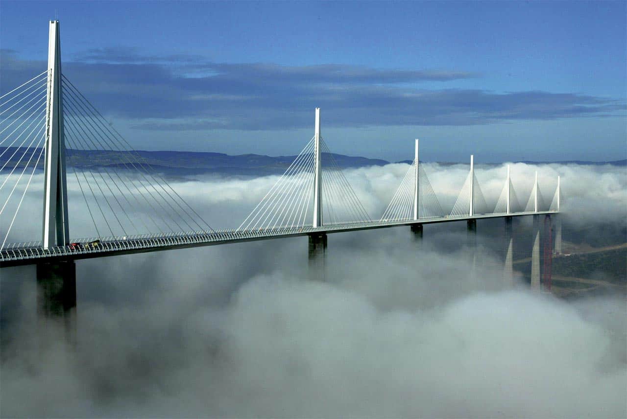
The new Forth crossing is like many large bridge projects today, a cable-stayed bridge. In these, the stresses are transferred to the bridge towers and carried downward, rather than being transferred transversely by suspension cables which need to be anchored in the ground. This allows the deck to be built in sections, outward from the towers, rather than having to wait until the cables are fully constructed before hanging the roadway from them. Other notable cable-stayed designs include the QEII bridge east of London, the Pont de Normandie across the seine in northern France, and the lofty Milau viaduct in Southern France.
All of these constructions share a frugality of materials; typically using only two: steel and masonry, often concrete, which combines strength and versatility with cheapness. For this reason, major structural innovations are thought unlikely unless other materials are developed that can challenge the existing ones in value, as steel did with cast and wrought iron. Innovations in monitoring are likely throughout bridge structures, to give earlier warning of component failure as happened with the Forth Road Bridge; self-healing concrete is also being considered for towers and decks.
The Engineer would like to acknowledge the assistance of Professor Mark Miodownik and Roma Agrawal with this feature.
To read the views of the global leader for bridge design at engineering consultancy and contractor Arup, Naeem Hussein, click here.


Red Bull makes hydrogen fuel cell play with AVL
Formula 1 is an anachronistic anomaly where its only cutting edge is in engine development. The rules prohibit any real innovation and there would be...