Sep 1856: Ploughing ahead

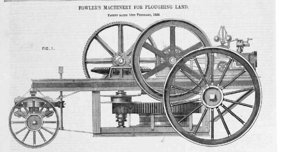
In September 1856, The Engineer reported on one of the latest developments in mechanised farming: Fowler's steam-driven plough. Jason Ford reports

steam-driven plough

John Fowler’s career as an agricultural engineer was inspired in part by a visit to Ireland in 1849 where he witnessed crop failure – and incredible human suffering - due to poor drainage.

On his return to England, he set about developing a horse powered drainage engine that would overcome the failings of the mole plough, a device used for drainage that is still in use today to lay small diameter pipes. In the nineteenth century, however, the mole plough was hamstrung by the need for considerable tractive power, which limited the size of the plough.

READ THE ORIGINAL STORY FROM THE ENGINEER'S ARCHIVE

His first two efforts saw horses turn a winch to pull the ploughs across a field with ropes, but by 1856 he had replaced horses with steam and came to realise that his ‘ploughing engines’ could replace horses to do the job of cultivation a well as cutting drainage channels.

Fowler’s machine was quick but is said to have fallen down on cost; a horse and ploughman could cultivate one acre of land for 7s compared to 7s 2.5d. Undeterred, Fowler and various collaborators were granted 32 patents between 1850 and 1864 for machinery that included ploughs and plough apparatus, reaping machines, seed drills, traction engines and slide valves.

In September 1856 one of his patented steam-driven ideas had come to the attention of The Engineer. The system can be described most simply as a pair of stationary machines that pull a plough across a field to cut furrows. The machines are then repositioned after each cut and the process is repeated until the field is completed.

Explaining the operation of the system The Engineer wrote:  “when working with a subsoil plough, an upright or horizontal barrel or capstan is combined on the same frame, platform, or base plate, with an engine which gives motion to it, by which capstan or barrel the subsoil plough is moved by a wire rope, and there is a second barrel for moving by another wire rope the engine and capstan from point to point along the headland.

“The machinery is arranged to make a direct pull on the plough and is moved a distance each time equal to that between drain and drain,” our Victorian predecessor noted.

“Another improvement relates to the anchor or instrument used for holding on or resisting the movement of the engine, capstan, or barrel and pulleys when working with drain, subsoil, or other ploughs by power,” The Engineer said. “For this purpose a plate or frame is used, which, when employed, is placed upright in a hole. On this plate or frame is hinged a lever, to the upper end of which a chain or rope is fixed. The lower end of this lever is formed with a broad end or plate, which, when the lever is pulled on, rests against the opposite side of the hole, and very securely anchors the engine and machinery which gives motion to the plough, and when pulleys are used they are similarly anchored.”

The front wheels were locked and attached to them was a toothed arc working with a pinion that had a handle at its upper end for steering. A steam driven piston and connecting rod on the crank shaft helped to provide motion.

A fly wheel was installed at one end of the crank shaft and a pinion at the other to drive the toothed wheel on the axis. At the upper end of the vertical axis was a bevelled wheel driven by the pinion.

“A drum on the axis is used for moving the machine from place to place, for which purpose one end of a rope is made fast to an anchor placed in the direction in which it is desired to move the machine, and the other end of the rope is passed round a drum,” said The Engineer. “On the axis there is another pinion which drives the toothed wheel on the upright axis and keyed on to the axis is a barrel or capstan, round which the rope is passed by which the plough is hauled, the rope passing direct from the barrel to the plough.

“When at work, the machine [is] firmly anchored by a chain which is attached to the frame underneath the axis of the main drum, and this attachment is so made that the chain can be easily slipped without taking the strain off it. To supply the machine with steam, a boiler is used which is mounted on wheels by itself; it is coupled to the machine, and has a flexible steam pipe for conducting the steam to the cylinder.

MORE FROM THE CLASSIC ARCHIVE HERE