Rigours of wind prompt Ricardo bearing rethink

The rigours of turbine operation have prompted a rethink on bearing design. Dave Wilson reports

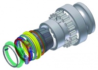
High in the air and buffeted by gusts and gales, wind-turbine gearboxes present a range of opportunities for failure. The durability of these bearings is therefore key – especially on offshore wind farms, where cost of maintenance is high.

Engineers at Ricardo, who have developed cost models for gearbox-maintenance activities, estimate the typical cost of a repair arising from the failure of certain bearings at €430,000 (£370,000) for an installation 20km offshore. This is based on a North Sea installation with average weather patterns for a fault arising in October. The high cost and long downtime threatens the viability of commercial offshore installations, but also provides the opportunity for engineers to add value to a component that may cost less than €1,000 (£870).

Ricardo has designed a solution that it believes could make the service life of bearings in such gearboxes six times longer. Funding from a share of £3m, provided by the Northern Wind Innovation Programme (NWIP), will see the company work with a manufacturer of large industrial bearings and academics at Sheffield University to take the concept further.

Forensic investigation undertaken by Ricardo had already unearthed some classic bearing faults. Some were due to unequal load distribution applied to the bearings in epicyclic gears. Others arose after running at partial turbine power, when the rolling elements are prone to skid rather than roll and cause. This causes scuffing of the precision-ground surfaces.

’Irrespective of the cause, wear was most pronounced on the fixed inner bearing ring of the planetary bearing in the gearbox, where it was concentrated over a 40o arc. That wear can lead to premature failure, while the remainder of the ring remains unworn. We realised that if we could address this issue, we could increase the lifetime of the gearbox,’ said Jonathan Wheals, Ricardo’s chief engineer.

Wheals’ design team was aware that any new design would need to be able to be retrofitted to turbine gearboxes due for refurbishment, as well as used in new designs.

Initially, the team considered introducing additives to the oil used in the gearbox. However, they discovered that, while many additive manufacturers claimed that their products would prolong the life of the bearings, they were not prepared to back their claims with a warranty.

Next they considered coating the race of the bearing with diamond-like coatings, or using ceramic elements in the race. Both of these approaches were discounted, as the team realised that the unpredictable failure mode of the coatings and the ceramic components under shock loads could potentially damage the entire gearbox.

Using plain bearings was another alternative that was rejected, due to the fact that the aspect ratio of bushes is so different to that of their rolling counterparts that a totally different packaging envelope would be required.

The team also looked at the possibility of using tilting pad bearings, but these were unsuitable for use where mass and space are critical.

’The most pragmatic solution involved rotating the fixed inner race of the bearing, such that the wear would be distributed around the full circumference of the race. This would ensure that the fatigue damage or wear never reached a critical condition during the turbine life and would be applicable to the outer races of bearings used in direct-drive turbines,’ said Wheals.

The first approach that the team devised involved gearing the outer race to rotate the inner race with a flex-spline drive that would cause the inner race to rotate at 1/120 of the speed of the outer race. While the approach would certainly have distributed the wear on the inner race, the additional flex-spline drive might have its own fatigue issues and the debris that resulted from its failure might also cause a rapid bearing failure.

They then considered rotating the inner race by using jets of lubricant that impinged upon miniature Pelton wheels in the side face of the inner race to generate rotating forces. Wheals estimated that 200Nm of torque could easily be generated by such a system to rotate the race when supported by a hydrostatic film.

’Customers wanted to know how we could positively index the race to avoid a known band on that inner race that is damaged, or audit and control that bearing positively rather than rotating it in an ad hoc way,’ said Wheals. This led the team to consider a method by which they could disengage the shaft into the gearbox, so that the inner race of the gear could be rotated then re-engaged after the operation had taken place. The action would need to be performed in a manner that could be easily quantified.

It is common practice to connect large bearings onto shafts using a hollow conical sleeve that is forced between the inner race of the bearing and the shaft by hydraulic pressure of 1,000 bar, typically. The technique allows such an arrangement to be disassembled in the field.

Basing their system on this principle, the team modified it substantially to meet their more rigorous demands. They developed a solution that would allow the shaft to be disconnected from the bearing using just 10bar hydraulic pressure, allowing them to use part of the existing hydraulic supply within the turbine that is already used for lubrication.

In their design, a conical sleeve is forced between the inner race of the bearing and the shaft by a large Belville spring that maintains the race on the cone during normal operation. The race is released for rotation by the prior rotation of a roller ramp that releases the load from the spring. The cone is then positively dragged away from the ring, whereupon it is free to rotate. Hydrostatic channels on the cone ensure ease of separation of the cone from what might be a corroded surface after a long period of engagement.

The roller ramp itself is driven by an actuation ring whose movement is controlled by an oscillating ratchet that can operate at 10bar with the conventional bulk gearbox oil. The actuation ring is held in place by a spring-loaded finger, or pawl, that moves forward when hydraulic pressure is applied and is prevented from counter rotating by a latch. If oil pressure is lost at any time, the Belville spring re-engages the cone, providing a failsafe mechanism.

As it was important to determine the exact degree of bearing rotation, the team deployed a ’percussion bell’ – a mechanical device that amplifies the acoustic signal caused by the pawl as the actuation ring is rotated and transmits it though the structure of the gearbox. Then, by detecting and processing the signals using accelerometers and control systems that already exist on wind-turbine gearboxes for monitoring bearing condition, the position can be accurately determined.

With the design finalised, the team will now work with production engineers at a UK manufacturer of large industrial bearings to develop system prototypes. Prof Dwyer-Joyce, head of Mechanical Engineering at Sheffield University, and his team will develop theory to define the optimal strategy.

Testing will be carried out at Ricardo’s Leamington facility and will then be independently verified by Prof Dwyer-Joyce’s team. Acoustic emission techniques will provide insight into the failure mode achieved during the accelerated testing. Further instrumentation will be installed to measure the oil-film thickness in the load region and inform the wear/damage prediction model that will be used to command the indexing strategy.

A standard-bearings sample will be tested under accelerated conditions to establish a baseline. The concept will then be tested under these conditions.

’When fully developed, the new bearing technology should provide a five-fold increase in bearing life, in comparison with existing rolling-element bearing technology used in wind turbines,’ said Wheals.

The key facts to take away from this article

» The sleeve enables the shaft to be disconnected using 10bar pressure
» Hydrostatic channels on the cone allow separation from the surface
» A spring-loaded pawl moves forward under hydraulic pressure
» If oil pressure is lost, the Belville spring re-engages the cone