
Richard Anslow, System Applications Engineer and
Dara O’Sullivan, System Applications Manager
Conservative estimates suggest that there are at least one-quarter of a million wind turbines currently installed worldwide. In the next four years, the global wind turbine market is expected to add 278 GW of onshore and 44.3 GW of offshore capacity.1 This equates to at least 100,000 3 MW wind turbines. With this growth in renewable energies, and power input to national electricity grids, the reliable operation of wind turbine (WT) installations is the subject of significant research by industry and government bodies. Quantitative studies of WT reliability have shown that reliability has increased over time. For example, the 2016 U.S. national Renewable Energy Laboratory report2 has shown that the reliability of most WT subsystems, including gearboxes, has improved between 2007 and 2013, with a seven-fold decrease in gearbox downtime. However, in 2018 gearboxes remained one of the three most likely failure sites with the highest material cost.2,3
The gearbox has the highest average cost per failure with a major replacement costing €230,000 on average.4
The relatively poor reliability of gearbox components has led to an emphasis for condition monitoring for gearing, bearings, and shafts. In addition to the gearbox, the rotor blades and electrical generator are the WT system components with the highest failure rates.5,6 There are many commercially available wind turbine condition monitoring systems, the majority of which are targeted toward gearbox analysis using vibration sensors.7 There are some commercially available rotor blademonitoring systems7, but this is an area of ongoing research. A significant amount of literature exists to support the use of vibration monitoring systems in wind turbines,including detailed surveys and analysis of benefits of a variety of systems.8 Less well covered are vibration sensor requirements for wind turbine applications. This articleprovides system insights for wind turbine components, failure statistics, common fault types, and fault data gathering methods. Vibration sensor requirements,such as bandwidth, measurement range, and noise density are discussed in relation to common faults on WT components.
System Components, Faults, and Sensor Requirements
Figure 1 and Figure 2 illustrate the wind turbine system’s main components, with a detailed structure of the wind turbine gearbox. The following sections focus on the gearbox, blades, and tower requirements for condition monitoring, with a focus on vibration sensors. Other systems, such as the yaw drive, mechanical brake, and electrical generator are not generally monitored using vibration sensors, with torque, temperature, oil parameters, and electrical signals typically monitored.
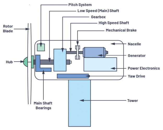
Figure 1. Wind turbine system components.
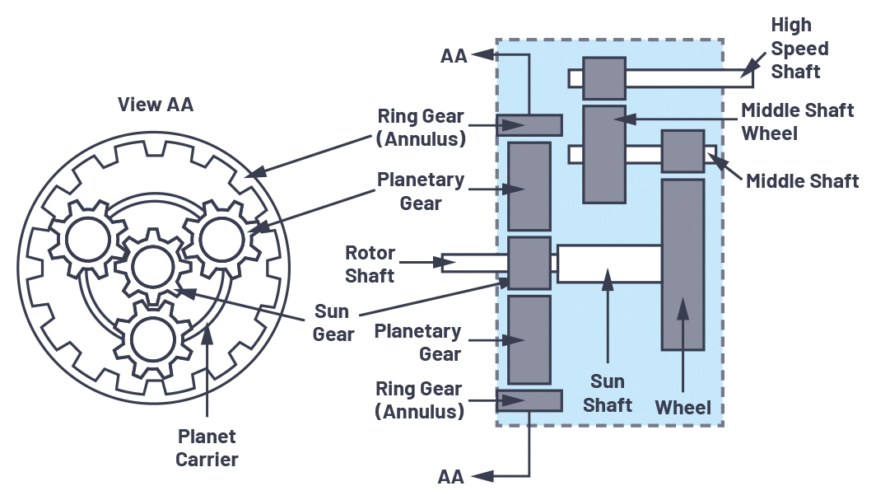
Figure 2. Gearbox structure.
Gearbox
The wind turbine gearbox transfers mechanical energy from the rotor hub with low rotational speed to the generator with high speed. Meanwhile, the WT gearboxsuffers alternating loads from varying wind speed and transient impulses of frequent braking actions. The gearbox consists of a low speed rotor shaft and main bearing, operating in the range of 0 rpm to 20 rpm (less than 0.3 Hz) from the wind force applied to the rotor blade. Capturing increased vibration signatures requires vibration sensors capable of operating right down to dc. Industry certification guidelines specifically note that 0.1 Hz performance is required from vibration sensors.9 The gearbox high speed shaft typically operates at 3200 rpm (53 Hz). To provide enough bandwidth to capture the harmonics of bearing and gear failures, vibration sensor performance up to 10 kHz and beyond is recommended for both low and high speed shafts.9 This is because bearing resonances are typically in the multikilohertz range, regardless of the rotational speed.10
Bearing failure is by far the largest contributor to gearbox failure. Some studies show catastrophic failure in gearwheels, with bearing failure as the root cause.11 When the rear bearing in the high speed shaft fails, the high speed shaft tilts, causing uneven transmission with the intermediate (middle) shaft gearwheel. The contacted teeth are prone to failure in this scenario, as shown in Figure 3.
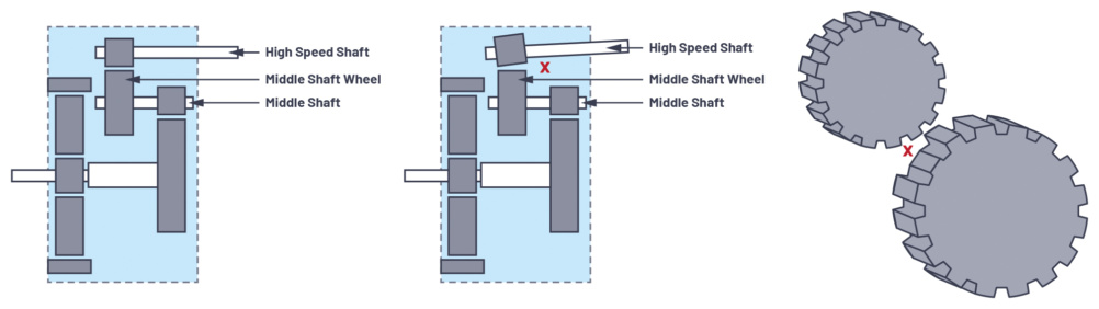
Figure 3. Middle shaft gearwheel broken teeth.
Bearing lubrication (oil) starvation has a strong contribution to main shaft bearing failure. Solutions such as SKF NoWear include a special bearing coating,12 which can help improve the time to oil starvation by greater than six-fold.
Even with special bearing coatings, and other gearbox improvement methods, there is still a need to monitor the gearbox main and high speed stage bearings with suitable vibration sensors. The vibration sensor needs to have a low enough noise floor so that early stage bearing faults with low vibration amplitude (g range) can be detected. Older MEMS technology, such as the ADXL001 with 4 mg/ noise floor can adequately capture bearing outer race faults.13 Figure 4 shows that outer race faults first present at approximately 0.055 g frequency peaks, with good bearing behavior presenting as less than 2 mg/ from a noise density perspective. The process gain of the data acquisition system in reference13 results in a large reduction in noise, which enables measurement of the 2 mg/noise floor.Using a sensor with a 4 mg/ noise floor will only be suitable if sufficient process gain is achieved in the DAQ system, and if the noise is stochastic. In general, it is better to use a vibration sensor with a 100 µg/ to 200 µg/ noise floor, rather than depending on process gain, which only works if the noise is stochastic andnoncorrelated.
A sensor with a 100 µg/ to 200 µg/ noise floor has sufficient performance to capture normal bearing operating conditions, as well as excellent performance whencapturing early stage faults in the mg/ range. In fact, using a MEMS sensor with 100 µg/ noise floor will enable even earlier detection of bearing faults.
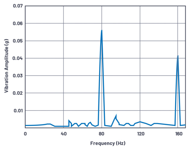
Figure 4. Bearing outer race faults measured using MEMS accelerometer ADXL001.
While initial bearing damage presents at less than 0.1 g, advanced bearing damage signatures typically occur at 1 g, which should trigger maintenance.14 Figure 5 shows that gearbox maintenance and bearing replacement can occur when the vibration amplitude exceeds 6 g. As previously noted, harmonics of bearing faults occur at higher frequencies. Measurements at higher frequency require a sensor with a larger g range specification. This is because the acceleration g force measured is proportional to the frequency squared. So, a small fault displacement at higher frequency results in a higher g range compared to the same fault displacement at low frequency. Higher bandwidth sensors, with measurement range up to 10 kHz, are generally specified for 50 g to 200 g, ideally specified for wind turbine applications. A vibration sensor needs to also cover shock loading conditions, due to structural impact or abrupt mechanical breaking. As a result, typical commercial vibration monitoring systems are rated to at least 50 g to 100 g full-scale range.
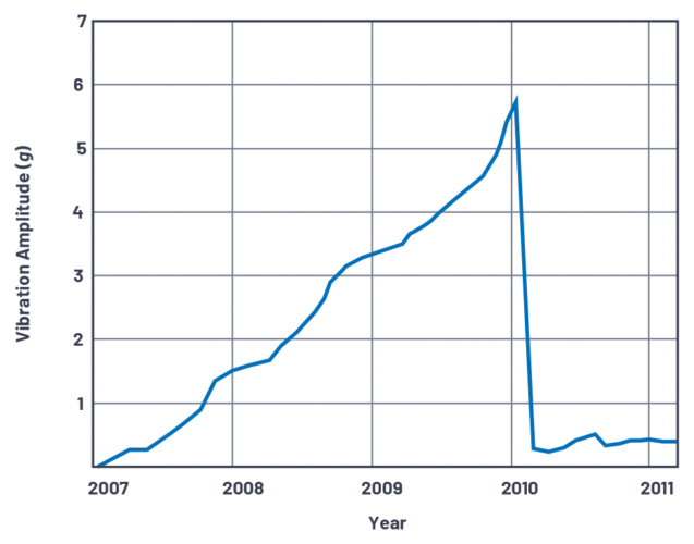
Figure 5. Bearing replacement at 6 g vibration amplitude.
For the wind turbine main bearing, at least one single-axis vibration sensor is required, with two recommended, and measurement in the axial and radial directions.9 Axial cracking in bearing races can shorten bearing life to as little as one to two years.15
Due to the complexity of the gearbox, as shown in Figure 2, at least six vibration sensors are recommended for condition monitoring.9 The number of sensors and position should be selected in such a way that all gear mesh and defect/rotation frequencies can be reliably measured. For the gearbox low speed stage, one single-axis sensor is required, placed as close as possible to the ring gear. For the intermediate and high speed stages, one single-axis sensor is required at the sun gear, middle shaft, and high speed shaft locations. Axial cracks on inner rings of high speed and intermediate speed bearings have become a leading cause of wind turbine gearbox life issues.15
For gearbox monitoring, future areas of improvement for condition monitoring include the adoption of wireless vibration monitoring systems, but sustainably powering these solutions is an area of ongoing research.8
Rotor Blade
Wind turbine rotor blades and the hub assembly capture wind and transmit torque at low speed. The primary causes of blade failure include extreme wind loads,environmental influences such as icing or lightning, and imbalance. These cause fractures and edge cracks, and failure in the pitch system. A limited number of commercial vibration monitoring systems exist, both internal and external to the blades.8 Numerous academic studies have been performed using MEMS vibration sensors on blades, such as the work of Cooperman and Martinez,16 that also include gyroscopes and magnetometers. The combined output of these sensors is usedto determine the orientation and deformation of wind turbine blade segments. In contrast, there are few commercial vibration monitoring systems available such asWeidmuller BLADEcontrol®, 17 which uses vibration sensors inside each rotor blade to measure changes to the natural vibration behavior of each rotor blade. The BLADEcontrol system is focused on the detection of extreme icing conditions on rotor blades causing excessive turbine vibration.
Generally, large-scale wind turbine blades (that is, 40 m and above in diameter) have their first natural frequencies in the range of 0.5 Hz to 15 Hz.18 Feasibility studies for a wireless vibration monitoring system on turbine blades18 show that blade frequency response due to vibration excitation extend significantly beyond the fundamental. Other studies19 show that blade frequencies due to blade edge deformation and blade torsional deformation are significantly different. Blade edge deformation natural frequencies occur in the 0.5 Hz to 30 Hz range, with blade torsional deformation natural frequencies occurring at up to 700 Hz. Measuring beyond the fundamental frequency with a vibration sensor requires larger bandwidth. The DNVGL certification of condition monitoring specification9 recommends using a vibration sensor for rotor blades capable of measuring in the 0.1 Hz to ≥10 kHz frequency range, with one sensor in the rotor axis and one sensor in the transversal direction. With high frequency measurement ranges possible on rotor blades, the vibration sensor must also have a large amplitude measurement range of at least 50 g, similar to the gearbox bearing requirements.
Tower with Nacelle
The wind turbine tower provides structural support for the nacelle housing and rotor blade assembly. The tower can suffer from impact damage, which can cause tower tilt. A tilted tower will result in nonoptimal blade angle relative to wind direction. Measurement of tilt requires a sensor that can operate right down to 0 Hz, as in zero wind conditions, so that the tilt can still be detected.
Structural damage to the foundation can lead to tower sway. Tower sway monitoring is built into some turbine condition monitoring systems, but there are few commercially available options in comparison to gearbox vibration monitoring.8 The Scaime condition monitoring system20 monitors blades, tower, and foundation using accelerometers, displacement sensors, strain sensors, and temperature sensors. The Scaime accelerometer full-scale range is quoted at ±2 g,20 and monitored frequencies need to be in the 0.1 Hz to 100 Hz range according to the DNVGL specification.9 As previously noted, the lower frequency limit reduces to 0 Hz in the case of a tower structural fault, causing tilt, in static conditions (no wind force). For tilt measurement, a sensor with excellent dc stability performance is required. MEMS sensors, such as the ADXL355, are available in hermetically sealed packages, which achieve industry-leading 0 g offset stability.
Studies21 validate that a vibration sensor with minimum ±2 g range is adequate for tower monitoring. Maximum wind speeds of 25 mps yield acceleration g levels of lessthan 1 g for towers in normal operating mode. In fact, the wind turbine in the “Identifiable Stress State of Wind Turbine Tower Foundation System Based on Field Measurement and FE Analysis”21 study is rated for a 2 mps to 25 mps wind speed, with wind turbine power down (cut out) at 25 mps wind speed.
Table 1. Vibration Sensor Requirements for Wind Turbine Condition Monitoring
| Component | No. of Sensors | Direction of Measurement | Frequency Range | Acceleration Range | Noise Density |
| Rotor blade | Two single axis | Axial and transversal | 0.1 Hz to ≥10 kHz | ±50 g (minimum) to 100 g | ≤1 mg/ required to capture |
| Main bearing | Two single axis | Radial and axial | 0.1 Hz to ≥10 kHz | ±50 g (minimum) to 100 g |
| Gearbox low speed (ring gear) | One single axis | Radial | 0.1 Hz to ≥10 kHz | ±50 g (minimum) to 100 g | ≤100 µg/ to 200 µg/ required to capture early state bearing faults |
| Gearbox mid to high speed (sun gear, middle, and high speed shafts) | Three single axis | Radial and axial | 10 Hz to ≥10 kHz | ±50 g (minimum) to 100 g |
| Generator bearing (inboard and outboard bearing) | Two single axis | Radial | 10 Hz to ≥10 kHz | ±50 g (minimum) to 100 g | ≤100 µg/ to 200 µg/ |
| Tower and nacelle | Two single axis | Axial and transversal | 0 Hz to ≥100 Hz | ±2 g (minimum) |
Summary
Table 1 provides a summary of vibration sensor requirements based on wind turbine application requirements. The number of sensors, direction of measurement, and frequency range is given in the DNVGL certification of condition monitoring specification.9 As previously noted, 0 Hz performance is important for monitoring tower structural issues. Table 1 also summarizes the appropriate amplitude range and noise density based on the field studies and measurements presented in thisarticle.
Fault Data Gathering Method
All large utility scale WTs have a standard supervisory control and data acquisition (SCADA) system principally used for parameter monitoring. Examples of monitored parameters include gearbox bearing temperature and lubrication, active power output, and phase currents. Some references6 discuss using SCADA data for condition monitoring of wind turbines to detect trends. A Durham University survey7 lists up to 10 commercially available condition monitoring systems, which can be adapted and fully integrated with existing SCADA systems using standard protocols. One example is GE Energy ADAPT.Wind.22 Broad surveys of future technology trends7 indicate a clear move toward installation of vibration monitoring systems on wind turbines.
Suitable Vibration Sensors for Wind Turbine Condition Monitoring
At or below 0.3 Hz, piezoelectric-based vibration technologies struggle or fail to capture vibration signatures. This means that low speed WT components such as rotor blades, the main bearing, the low speed gearbox, and the tower cannot be properly monitored. MEMS-based sensors, with performance right down to 0 Hz, can capture critical faults on all main wind turbine components. This provides the customer with a single vibration sensor solution for the WT, using MEMS only to measure faults from 0 Hz right up to 10 kHz and beyond.
| Technology Suitable for CbM of | Rotor Blade | Main Bearing | Gearbox Low Speed | Gearbox Mid and High Speed | Generator Bearing | Tower with Nacelle |
| MEMS | ✓ | ✓ | ✓ | ✓ | ✓ | ✓ |
| Piezoelectric | ✗ | ✗ | ✗ | ✓ | ✓ | ✗ |
In addition to being able to capture all critical faults, MEMS provide the following benefits:
- Wideg measurement range and ultralow µg/noisedensity, easily meeting the requirements noted in Table
- MEMS have a built-in self-test (BIST) The system operator does not need to access the WT to test/ensure correct sensor operation, saving costs. In comparison, piezoelectric-based technologies do not have a BIST capability.
- TheMEMSinterfaceismoreflexibleforbothdatainterfaceand power supply incomparisontopiezoelectric-basedTherearelimitedoptionsto translatethehighimpedancepiezoelectricsensoroutputtoalong cable. The most common implementation is the 2-wire IEPE interface, which powers the piezoelectric sensor on a shared power/data line with a second ground wire. IEPE uses an amplifier matched to the piezoelectric to provide a low impedance cable drive solution. IEPE interface solutions are possible with MEMS sensors, but MEMS sensors also allow easier integration with existing systems that operate using field bus (RS-485, CAN) or Ethernet-based networks. This is because MEMS sensors are available with analog output or digital output (SPI, IC), which can be easily transferred to otherprotocols.
- Environmental performance: WT will generally operate in –40°C to +55°C temperatures, with MEMS devices easily meeting this
- MEMS have better sensitivity/linearity over time in comparison to piezoelectric-based sensors. The nonlinearity of Analog Devices’ accelerometers is low enough that it can most often be ignored. For example, the ADXL1001 MEMS accelerometer has a typical nonlinearity specification of less than 0.025% over full-scale range. In comparison, academic studies with standardized measurements of piezoelectric-based sensors report 0.5% or less nonlinearity.23
MEMS-Based Vibration Sensors and Solutions Available Today
Sensors
Meeting all of the bandwidth, range, and noise density requirements for vibration monitoring in wind turbine applications is easily achieved using the ADXL1002, ADXL1003, ADXL1005, and ADcmXL3021 MEMS sensors (noted in Table 2). The ADXL355 and ADXL357 are also suitable for wind turbine tower monitoring, with lower bandwidth and range measurement performance. The ADXL355/ADXL357 have excellent dc stability, which is important for measuring wind turbine tower tilt. The ADXL355/ADXL357 hermetic package ensures excellent long-term stability. Over a 10-year lifetime the ADXL355 repeatability is within ±3.5 mg, providing a highly accurate sensor for tilt measurement.
Table 2. Suitable MEMS Sensors for Wind Turbine Condition Monitoring
| MEMS Sensor | No. of Axes | Range (±g) | Bandwidth (kHz) | Noise Density (µg/√Hz) |
| ADXL355 | 3 | 2, 4, 8 | 0 to 1 | 25 |
| ADXL357 | 3 | 10, 20, 40 | 0 to 1 | 80 |
| ADXL1005 | 1 | 100 | 0 to 23 | 75 |
| ADXL1003 | 1 | 200 | 0 to 15 | 45 |
| ADXL1002 | 1 | 50 | 0 to 11 | 25 |
| ADcmXL3021 | 3 | 50 | 0 to 10 | 26 |
Solutions for Wind Turbine Condition Monitoring
Wireless
Analog Devices offers a complete suite of validated reference designs, evaluation systems, and plug and play machine health sensor modules to accelerate customer design efforts. Figure 6 shows Analog Devices’ wireless vibration monitoring evaluation platform. This system solution combines mechanical attachments, hardware, firmware, and PC software to enable rapid deployment and evaluation of a single-axis vibration monitoring solution. The module can be directly attached to a motor or fixture, either magnetically or via a stud. It can also be combined with other modules on the same wireless mesh network to provide a broader picture with multiple sensor nodes as part of a condition-based monitoring (CbM) system.
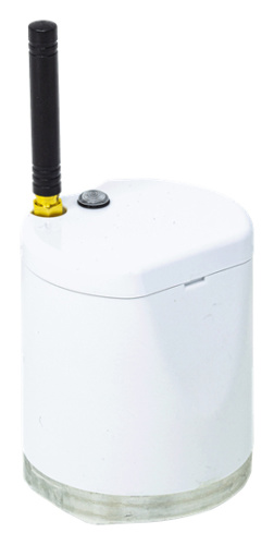
Figure 6. Wireless vibration monitoring evaluation platform.
The CbM hardware signal chain consists of a single-axis ADXL1002 accelerometer mounted to the base of the module. The output of the ADXL1002 is read into the ADuCM4050 low power microcontroller, where it is buffered, transformed to frequency domain and streamed to the SmartMesh® IP mote. From the SmartMesh chip,the ADXL1002’s output is wirelessly streamed to the SmartMesh IP manager. The manager connects to a PC and visualization and saving of the data can take place. Data is displayed as raw time-domain data and FFT data. Additional summary statistics information on the time-aggregated data are available. The full Python® code of the PC-side GUI, as well as the C firmware deployed to the module, is made available to enable customer adaptation.
Wired
Analog Devices’ Pioneer 1 wired CbM evaluation platform provides an industrial wired link solution for the ADcmXL3021 triaxial vibration sensor. The CbMhardware signal chain consists of a triaxial ADcmXL3021 accelerometer with a Hirose flex PCB connector. The ADcmXL3021 Hirose connector with SPI and interruptoutputs are attached to interface PCBs, which translate SPI to an RS-485 physical layer over meters of cabling to a remote master controller board. The SPI toRS-485 physical layer translation can be achieved using isolated or nonisolated interface PCBs, which include iCoupler® isolation (ADuM5401/ADuM110N) and RS-485/RS-422 transceivers (ADM4168E/ADM3066E). This solution combines power and data over one standard cable, which reduces cable and connector costs atremote MEMS sensor nodes. Dedicated software GUI enables simple configuration of the ADcmXL3021 device, and vibration data capture over long cables. GUI software enables data visualization as raw time domain or FFT waveforms.
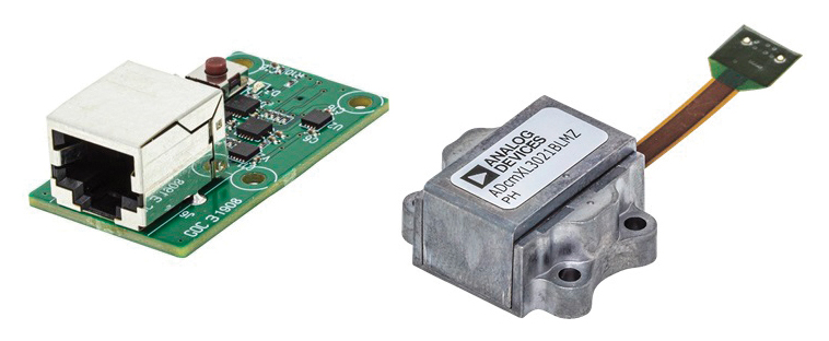
Figure 7. Wired vibration monitoring evaluation platform.
Conclusion
This article has demonstrated that MEMS-based sensors can measure all critical faults on a wind turbine’s critical system components. MEMS sensor bandwidth, measurement range, dc stability, and noise density are ideally specified, with excellent performance in wind turbine applications.
MEMS built-in self-test (BIST), flexible analog/digital interfaces, and excellent sensitivity/linearity over time are additional reasons why MEMS sensors are the best solution for wind turbine condition monitoring. Maintaining systems to detect early errors based on vibrations is a modern technology to prevent the costly downtime of a complete wind turbine.
References
1 Global Wind Report 2018. GWEC, April 2019.
2 Shuangwen (Shawn) Sheng. “Wind Turbine Gearbox Reliability Database, Condition Monitoring, and Operation and Maintenance Research Update.” Drivetrain Reliability Collaborative Workshop, May 2016.
3 Alexios Koltsidopoulos Papatzimos, Tariq Dawood, and Phillip R. Thies. “Data Insights from an Offshore Wind Turbine Gearbox Replacement.” EERA DeepWind’2018, 15th Deep Sea Offshore Wind R&D Conference, Journal of Physics: Conference Series, October 2018.
4 James Carroll, Alasdair McDonald, and David McMillan. “Failure Rate, Repair Time, and Unscheduled O&M Cost Analysis of Offshore Wind Turbines.” Wind Energy, August 2015.
5 Yao Li, Caichao Zhu, Chaosheng Song, and Jianjun Tan. “Research and Development of the Wind Turbine Reliability.” International Journal of Mechanical Engineering and Applications, 2018.
6 Jannis Tautz-Weinert and Simon J. Watson. “Using SCADA Data for Wind Turbine Condition Monitoring—A Review.” IET Renewable Power Generation, Vol. 11, No. 4, May 2017.
7 Christopher J. Crabtree, D. Zappala, and P.J. Tavner. Survey of Commercially Available Condition Monitoring Systems for Wind Turbines. Durham Research Online, Durham University, May 2014.
8 Mathew L. Wymore, Jeremy E. Van Dam, Halil Ceylan, and Daji Qiao. “A Survey of Health Monitoring Systems for Wind Turbines.” Renewable and Sustainable Energy Reviews, Vol. 52, December 2015.
9 DNVGL-SE-0439 Service Specification: Certification of Condition Monitoring. DNVGL, June 2016.
10 Robert Bond Randall. Vibration‐Based Condition Monitoring: Industrial, Aerospace, and Automotive Applications. John Wiley & Sons, Inc., December2010.
11 Wei Teng, Xian Ding, Xiaolong Zhang, Yibing Liu, and Zhiyong Ma. “Multifault Detection and Failure Analysis of Wind Turbine Gearbox Using Complex Wavelet Transform.” Renewable Energy, Vol. 93, August 2016.
12 David de Garavilla and Dr. Xiaobo Zhou. “Extending Main-Shaft Bearing Life in Wind Turbines.” Windpower Engineering and Development, August 2019.
13 Eric Bechhoefer, Mathew Wadham-Gagnon, and Bruno Boucher. Initial Condition Monitoring Experience on a Wind Turbine. Annual Conference of Prognostics and Health Management Society, 2012.
14 Xavier Escaler and Toufik Mebarki. “Full-Scale Wind Turbine Vibration Signature Analysis.” Machines, 2018.
15 Nic Sharpley. “Understanding the Root Causes of Axial Cracking in Wind Turbine Gearbox Bearings.” Windpower Engineering and Development, April 2014.
16 Aubryn M. Cooperman and Marcias J. Martinez. “MEMS for Structural Health Monitoring of Wind Turbine Blades.” Conference: International Conference on Adaptive Structures and Technologies (ICAST 2014), October 2014.
17 BLADEcontrol. Weidmüller Interface GmbH & Co. KG, February 2020.
18 O.O. Esu, S.D. Lloyd, J.A.Flint, and S.J. Watson. “Feasibility of a Fully Autonomous Wireless Monitoring System for a Wind Turbine Blade.” Renewable Energy, Vol. 97, November 2016.
19 L.K. Tartibu, M. Kilfoil, and A.J. Van Der Merwe. “Vibration Analysis of a Variable Length Blade Wind Turbine.” International Journal of Advances in Engineering & Technology, July 2012.
20 Wind Energy. Scaime, February 2020.
21 Chikako Fujiyama, Kaoru Yonetsu, Takuya Maeshima, and Yasuhiro Koda. “Identifiable Stress State of Wind Turbine Tower-Foundation System Based on Field Measurement and FE Analysis.” Procedia Engineering, Vol. 95, December 2014.
22 “Bently Nevada ADAPT.Wind: Condition Monitoring Solution.” Baker Hughes Company, November 2019.
23 J. Putner, P.B. Grams, and H. Fastl, “Nonlinear Behavior of Piezoelectric Accelerometers.” Conference: Fortschritte der Akustik, AIA-DAGA 2013, March 2013.
“Evaluation of Ice Detection Systems for Wind Turbines: Final Report VGB Research Project No. 392: Final Report.” METEOTEST, February 2016.
Fischer, Katharina and Diego Coronado. “VGB Research Project 383— Condition Monitoring of Wind Turbines: State of the Art, User Experience, andRecommendations.” VGB PowerTech, July 2015.
Tchakoua, Pierre, Mohand Ouhrouche, René Wamkeue, and F. Slaoui Hasnaoui. “Wind Turbine Condition Monitoring: State-of-the-Art Review, New Trends, and Future Challenges.” Energies, April 2014.
Teng, Wei, Feng Wang, Kaili Zhang, Yibing Liu, and Xian Ding. “Pitting Fault Detection of a Wind Turbine Gearbox Using Empirical Mode Decomposition.” Journal of Mechanical Engineering, 2014.
About the Author
Richard Anslow is a systems applications engineer with the Connected Motion and Robotics Team within the Automation and Energy business unit at Analog Devices. His areas of expertise are condition-based monitoring and industrial communication design. He received his B.Eng. and M.Eng. degrees from the University of Limerick, Limerick, Ireland. He can be reached at richard.anslow@analog.com.
About the Author
Dara O’Sullivan is a system applications manager with the connected motion and robotics team within the Automation and Energy Business Unit at Analog Devices. His area of expertise is power conversion, control, and monitoring in industrial motion control applications. He received his B.E., M.Eng.Sc., and Ph.D. from University College Cork, Ireland, and he has worked in industrial and renewable energy applications in a range of research, consultancy, and industry positions since 2001. He can be reached at dara.osullivan@analog.com.


Water Sector Talent Exodus Could Cripple The Sector
Maybe if things are essential for the running of a country and we want to pay a fair price we should be running these utilities on a not for profit...