Luca Martini, System Engineer, Analog Devices
Why Is DC Energy Metering Important?
In the 21st century, world governments are working on action plans to tackle complex and long-term challenges in reducing CO2 emissions. CO2 emissions have been proven responsible for the devastating effects of climate change, and the needs of new efficient energy conversion technology and improved battery chemistry are rapidly growing.
Including both renewable and non-renewable energy sources, the world population consumed nearly 18 trillion kWh last year alone and demand keeps growing; in fact more than half of the energy ever generated has been consumed in the last 15 years.
Our electrical grids and power generators are constantly expanding; the need for more efficient and environmentally friendly power has never been greater. Because it was easier to use, early grid developers worked with alternating current (ac) to feed power to the world, but in many areas, direct current (dc) can dramatically improve efficiency.
Driven by the development of efficient and economic power conversion technology based on wide band gap semiconductors, such as GaN and SiC devices, many applications now see benefits in switching to dc energy exchange. As a consequence of that, precision dc energy metering is becoming relevant, especially where energy billing is involved. In this article, opportunities for dc metering in electric vehicle charging stations, renewable energy generation, server farms, microgrids, and peer-to-peer energy sharing will be discussed, and a dc energy meter design will be proposed.
DC Energy Metering Applications
DC Electric Vehicle Charging Stations
The growth rate of plug-in electric vehicles (EVs) is estimated at +70% CAGR as of 20181 and projected to grow +25% CAGR year by year from 2017 to 2024.2 The charging station market will follow at 41.8% CAGR from 2018 to 2023.3 However, to accelerate the reduction of the CO2 footprint caused by private transportation, EVs need to become the first choice for the automotive market.
In recent years great effort went into improving the capacity and lifetime of batteries, but a widespread EV charging network is also a fundamental condition to allow long trips without concerns about range or charging time. Many energy providers and private companies are deploying fast chargers up to 150kW, and there is strong interest in ultrafast chargers with power up to 500kW per charging pile. Considering ultrafast charging stations with localised charging peak power up to megawatts and associated fast-charge energy premium rates, EV charging will become a massive energy exchange market, with the consequent need of accurate energy billing.
Currently, standard EV chargers are metered on the ac side with the drawback of no measurement of the energy lost in the ac-to-dc conversion and, consequently, billing is inaccurate for the end customer. Since 2019, new EU regulations are forcing energy providers to bill the customer only for the energy transferred to the EV, making the power conversion and distribution losses borne by the energy supplier.
While state-of-the-art SiC EV converters can reach efficiency above 97%, there is a clear need to enable accurate billing on the dc side for fast and ultrafast chargers, where energy is transferred in dc when directly connected to the battery of the vehicle. In addition to public EV charging metering interests, private and residential peer-to-peer EV charging schemes might have even more incentive for precise energy billing on the dc side.
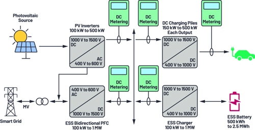
Figure 1. DC energy metering in the EV fuel station of the future.
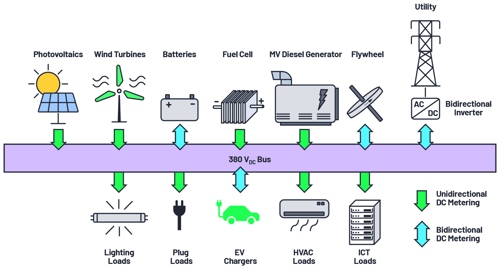
Figure 2. DC energy metering in a sustainable microgrid infrastructure.
DC Distribution - Microgrids
What is a microgrid? In essence, a microgrid is a smaller version of a utility power system. As such, safe, reliable, and efficient power is required. Examples of microgrids can be found in hospitals, on military bases, and even as part of the utility systems where renewable generation, fuel generators, and energy storage are working together to make a reliable energy distribution system.
Other examples of microgrids can be found in buildings. With the wide deployment of renewable energy generators, buildings can even become self-sufficient, with rooftop solar panels and small-scale wind turbines generating as much energy as is used, independent but backed up by the grid.
Moreover, as much as 50% of a building’s electric loads run on dc. Currently each electronic device must convert ac to dc power, and up to 20% of energy is lost in the process, with a total savings estimated up to 28% vs. traditional ac distribution.4
In a dc building, energy consumption can be decreased by converting ac to dc all at once and feeding dc directly to the appliances that need it, such as LED lights and computers.
Interest in dc microgrids is rapidly growing, as is the need for standardisation.
IEC 62053-41 is a pending standard that indicates requirements and nominal levels for residential dc systems and enclosed type meters similar to the ac equivalent for dc energy metering.
The dc microgrid segment is valued at around $7 billion as of 20175 and will see further growth from the emerging dc distribution trend.
DC Data Centre
Data centre operators are actively considering different technologies and solutions to improve the power efficiency of their facilities, as power is one of their largest costs.
Data centre operators see relevant benefits in dc distribution as the minimum number of conversions required between ac and dc decreases, and the integration with renewable energy is easier and more efficient. The reduction of conversion stages is estimated as:
- 5% to 25% energy savings: increase in transmission and conversion efficiencies, and less heat generation
- 2× reliability and availability
- 33% floor space reduction
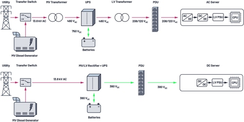
Figure 3. Fewer components are required in a dc supply for data centres, and there are lower losses than with traditional ac distribution.
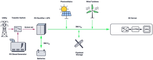
Figure 4. Renewable energy integration in a dc data centre.
Distribution bus voltages range up to around 380VDC, and accurate dc energy metering is gaining interest since many operators are switching to the more measurable approach of charging the colocation customer by power use.
The two most popular ways to charge colocation customers for power usage are:
- Per whip (flat fee for each outlet)
- Consumed energy (metered outlet - power charged for each kWh consumed)
With a view toward encouraging power efficiency, the metered output approach is gaining popularity and customer pricing can be described as:
Recurring cost = space fee + (meter reading for IT equipment × PUE)
- Space fee: fixed, includes security and all the building operational costs
- Meter reading for IT equipment: the number of kWh consumed by the IT equipment multiplied by the cost of energy
- Power usage effectiveness (PUE): takes into account the efficiency of the infrastructure behind IT, such as cooling
A typical modern rack consumes up to 40kW of dc power. Therefore, currents up to 100A are required to be monitored with billing-grade dc meters.
Challenges in Precision DC Energy Metering
In the early 1900s traditional ac energy meters were entirely electromechanical. The combination of a voltage and a current coil was used to induce eddy currents in a rotating aluminium disc. The resulting torque on the disc was proportional to the product of the magnetic flux generated by the voltage and current coils. Finally, the addition of a breaking magnet for the disc made the rotational speed directly proportional to real power consumed by the load. At this point, measuring the energy consumed is simply a matter of counting the number of rotations over a period of time.
Modern ac meters are significantly more complex, accurate, and protected from tamperings. Now, a state-of-the-art smart meter can even monitor its absolute accuracy and detect signs of tampering 24/7 while installed in the field. This is the case for the Analog Devices ADE9153B metering IC, enabled with mSure® technology. Energy meters - either modern, traditional, ac, or dc - are all classified by their impulses per kWh constant and percentage class accuracy. The number of impulses per kWh denotes the energy update rate, or resolution. The class accuracy certifies the maximum measure error of the energy.
Similar to the old mechanical meter, energy in a given time interval is calculated by counting these impulses; the higher the pulse frequency, the higher the instantaneous power, and vice versa.
DC Meter Architecture
The basic architecture of a dc meter is represented in Figure 5. In order to measure the power consumed by the load (P = V × I), at least one current sensor and one voltage sensor are required. When the low side is at earth potential, current flowing through the meter is commonly measured on the high side to minimise the risk of unmetered leakages, but current can also be measured on the low side, or both sides if required by the design architecture. The technique of measuring and comparing currents on both sides of the load is often used to enable the meter with fault and tamper detection capability. However, when the current is measured on both sides, at least one current sensor needs to be isolated in order to deal with the high potential across the conductors.
Voltage Measurement
Voltage is typically measured with a resistive potential divider, where a ladder of resistors is used to proportionally reduce the potential to a level compatible with the system ADC input.
Due to the large amplitude of the input signal, an accurate voltage measurement can be easily achieved with standard components. However, attention must be paid to temperature coefficients and voltage coefficients of the chosen component, in order to guarantee the required accuracy across the entire temperature range.
As previously discussed, dc energy meters for applications such as EV charging stations are sometimes required to bill exclusively for the energy transferred to the vehicle. In order to fulfil the measurement requirement, dc energy meters for EV chargers may be required to have multiple voltage channels, enabling the meter to sense the voltage also at the entry point of the vehicle (4-wire measurement). DC energy metering in a 4-wire configuration ensures that all the resistive losses of the charging pile and the cable are discounted from the total energy bill.
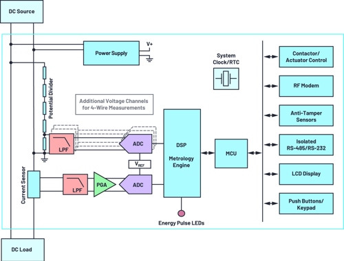
Figure 5. DC energy meter system architecture.
Current Measurement for DC Energy Metering
Electric current can be measured either by direct connection or indirectly, by sensing the magnetic field generated by the flow of the charge carrier. The next section will discuss the most popular sensors for dc current measurement.
Shunt Resistor
Direct connection current sensing is a tried and tested method of measuring ac and dc current. The flow of current is routed through a shunt resistor of known value. The voltage drop across the shunt resistor is directly proportional to the current flowing as described by the well-known Ohm’s law (V = R × I), and it can be amplified and digitised, providing an accurate representation of the current flowing in the circuit.
Shunt resistor sensing is a cheap, accurate, and powerful method for measuring current from mA to kA, with theoretically unlimited bandwidth. However, the method suffers from some disadvantages.
When current flows in a resistor, Joule heat is generated proportionally to the square of the current. This will cause not only losses in terms of efficiency, but the self-heating will change the shunt resistive value itself with a consequent accuracy degradation. To limit the self-heating effect, a low value resistance is used. However, when a small resistance is used the voltage across the sensing element is also small and sometimes comparable with the dc offset of the system. In these conditions, achieving the required accuracy on the low end of the dynamic range may not be a trivial task. State-of-the-art analogue front ends, with ultralow dc offset and ultralow temperature drift, can be used to overcome the limitations of small value shunt resistors. However, as operational amplifiers have a constant gain-bandwidth product, a high gain will limit the available bandwidth.
Low value current sensing shunts are usually made from specific metal alloys such as manganese-copper or nickel-chrome, which cancel the opposing temperature drifts of their constituents to result in an overall drift in the order of tens of ppm/°C.
Another error contributor in direct connection dc measurement can be the phenomenon of thermal electromotive force (EMF), also known as the Seebeck effect. The Seebeck effect is a phenomenon in which a temperature difference between at least two dissimilar electrical conductors or semiconductors forming a junction produces a potential difference between the two. The Seebeck effect is a well-known phenomenon, and it is widely used for sensing temperature in thermocouples.
In the case of 4-wire connected current shunts, the Joule heat will form on the centre of the resistive alloy element, propagating whilst the copper sensing wires, which may be connected to a PCB (or a different medium), and which may have a different temperature.
The sensing circuit will form a symmetric distribution of different materials; therefore, the potential at the junctions on the negative and positive sensing wires will approximately cancel. However, any difference in thermal capacity, such as a negative sensing wire being connected to a larger copper mass (ground plane), can produce a mismatch in the temperature distribution, resulting in a measure error caused by thermal EMF effect.
For that reason, attention must be reserved to the connection of the shunt and at the distribution of the generated heat.
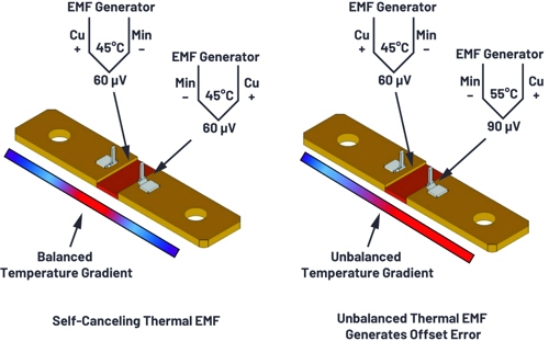
Figure 6. Thermal EMF in shunts caused by temperature gradient.
Magnetic Field Sensing - Indirect Current Measurement
Open-Loop Hall Effect
The sensor is constructed with a high magnetic permeability ring through which the sensed current wire is passed. This concentrates the magnetic field lines surrounding the measured conductor onto a Hall Effect sensor, which is inserted within the cross-section area of the magnetic core. The output of this sensor is preconditioned and usually available in different flavours. The most common are: 0V to 5V, 4mA to 20mA, or digital interface. While providing isolation and high current range for relatively low cost, absolute accuracies typically do not range below 1%.
Closed-Loop Hall Effect
A multiturn secondary winding on the permeable core driven by a current amplifier provides negative feedback to achieve zero total flux condition. By measuring the compensating current, linearity is improved and there is no core hysteresis with overall superior temperature drift and higher accuracy compared to the open-loop solution. Typical error ranges are down to 0.5%, but the additional compensation circuitry makes the sensor more expensive and sometimes limited in bandwidth.
Fluxgate
Is a complex open- or closed-loop system where the current is measured by monitoring the magnetic flux variations of an intentionally saturated core? A coil is wound around a high permeability ferromagnetic core that is intentionally saturated by a secondary coil driven by a symmetric square wave voltage. The inductance of the coil collapses every time the core approaches positive or negative saturation, and the rate of change of its current increases. The current waveform of the coil remains symmetrical unless an external magnetic field is additionally applied, in which case the waveform becomes asymmetrical. By measuring the size of this asymmetry, the intensity of the external magnetic field, and consequently the current that generated it, can be estimated. It provides good temperature stability and accuracy down to 0.1%. However, the complex electronics of the sensor makes it an expensive solution with prices 10 times higher than the other isolated solutions.
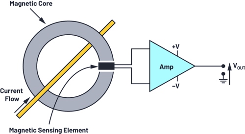
Figure 7. An open-loop current transducer based on a flux concentrator and magnetic sensor.
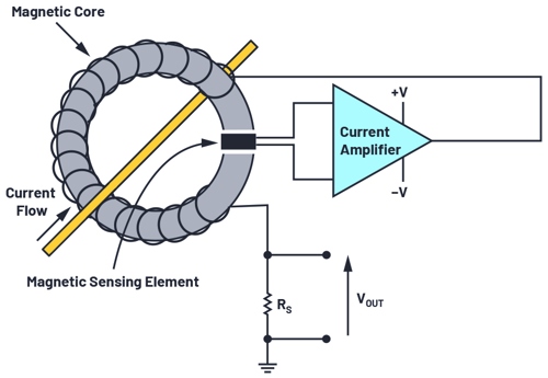
Figure 8. An example of the working principle of closed-loop current transducers.
DC Energy Metering: Requirements and Standardisation
While the standardisation of dc energy metering may not seem too difficult to achieve compared to the existing ac metering standards ecosystem, industry stakeholders are still debating the requirements for different applications, asking for more time to iron out the exact details of dc metering.
IEC is working on IEC 62053-41 in order to define requirements specific for dc static meters for active energy with accuracy classes of 0.5% and 1%.
The standard proposes a range of nominal voltages and currents, and sets limits on the maximum power consumption of the voltage and current channels of the meter. Moreover, like the ac metering requirement, specific accuracy is defined across the dynamic range, as well as the current threshold for no-load condition.
In the draft, there is no specific requirement for the bandwidth of the system, but a fast load variation test is required to be successfully accomplished, defining implicit requirement on the minimum bandwidth of the system.
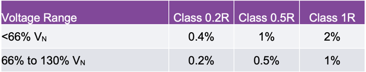
DC metering in EV charging applications is sometimes compliant with the German standard VDE-AR-E 2418 or old railway standard EN 50463-2. According to EN 50463-2, accuracies are specified per transducer, and the combined energy error is then a quadrature sum of voltage, current, and calculation error:

Table 1. Maximum Percentage Current Error per EN 50463-2
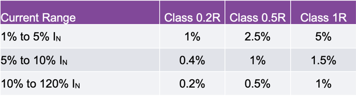
Table 2. Maximum Percentage Voltage Error per EN 50463-2
Conclusion: A Proof of Concept Standard Compliant DC Meter
Analog Devices is an industry leader in precision sensing technology, offering a complete signal chain for precision current and voltage measurements to meet the restrictive standards requirements. The next section will show a proof of concept for a dc energy meter compliant with the upcoming application-specific standard IEC 62053-41.
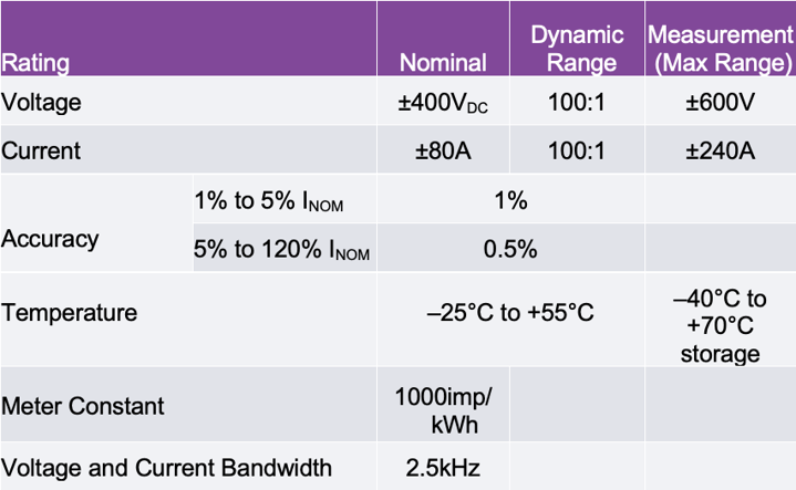
Considering the space of billing-grade dc energy metering in microgrids and data centres, we can hypothesize the requirements shown in Table 3.
Table 3. DC Energy Meter Specifications—Proof of Concept
Cheap and accurate current sensing can be achieved by using a small value and low EMF shunt (<1μVEMF/°C). Keeping the shunt resistance small is fundamental to reduce the self-heating effect and keep the power level below the limits required by the standard.
A commercial 75μΩ shunt will keep the power dissipated below 0.5W.
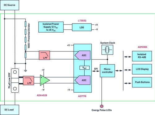
Figure 9. DC meter system architecture.
However, 1% of the 80A nominal current will generate a small signal of 60μV on a 75μΩ shunt, requiring a signal chain in the range of sub-microvolt offset drift performance.
The ADA4528, with a max offset voltage of 2.5μV and a max offset voltage drift of 0.015μV/°C, is well suited to provide ultralow drift, 100V/V amplification for the small shunt signal. Therefore, the simultaneous sampling, 24-bit ADC AD7779 can be directly connected to the amplification stage, with a 5nV/°C input referred offset drift contribution.
High dc voltage can be accurately measured with a resistive potential divider of 1000:1 ratio directly connected to the AD7779 ADC input.
Finally, a microcontroller implements a simple sample-by-sample, interrupt driven metrology functionality, where for each ADC sample the interrupt routine:
- Reads voltage and current samples
- Calculates instantaneous power (P = I × V)
- Accumulates the instantaneous power in an energy accumulator
- Checks if the energy accumulator exceeds the energy threshold to generate an energy pulse and clears the energy accumulation register
Moreover, in addition to the metrology functionality, the microcontroller enables system-level interfaces such as RS-485, LCD display, and push buttons.
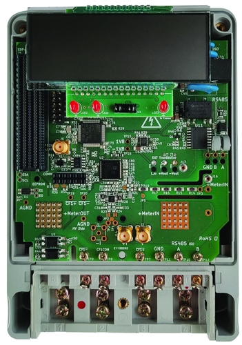
Figure 10. Proof of concept - prototype.
References
1 Tom Turrentine, Scott Hardman, and Dahlia Garas. “Steering the Electric Vehicle Transition to Sustainability.” National Center for Sustainable Transportation, UC Davis, July 2018.
2 “Global Electric Vehicle Market Report by Type (Battery Electric Vehicle, Hybrid Electric Vehicle, and Plug-In Hybrid Electric Vehicles), by Vehicle Type (Two Wheeler, Passenger Car, and Commercial Vehicles), and by Regions—Industry Trends, Size, Share, Growth, Estimation, and Forecast, 2017-2024.” Value Market Research.
3 Electric Vehicle Charging Stations Market by Charging Station (AC Charging Station, DC Charging Station), Installation Type (Residential, Commercial), and Region (North America, Europe, Asia Pacific, and Row)—Global Forecast to 2023. Research and Markets, April 2018.
4 Venkata Anand Prabhala, Bhanu Prashant Baddipadiga, Poria Fajri, and Mehdi Ferdowsi. “An Overview of Direct Current Distribution System Architectures and Benefits.” MDPI, September 2018.
5 “Global Microgrid Market by Type (AC Microgrid, DC Microgrid, Hybrid), Connectivity (Grid Connected, Remote/Island), Offering (Hardware, Services, Software), Power Source (Natural Gas, Solar, Fuel Cells, Combined Heat and Power, Diesel, and Others), Application (Healthcare, Industrial, Military, Electric Utility, and Educational Institutions), Region (North America, Europe, Asia Pacific, South America, and Middle East and Africa), Global Industry Analysis, Market Size, Share, Growth, Trends, and Forecast, 2018-2025.” Researchstore.biz.
About the Author
Luca Martini received an M.Eng. degree in electronics and telecommunication engineering for energy from the University of Bologna, Italy, in 2016. As part of his M.Eng. degree, he spent seven months at Fraunhofer IIS, Nuremberg, Germany, developing a precision real-time control system for the characterization of piezoelectric energy harvesters. From 2006 to 2016, Luca worked as a system and hardware developer in the biomedical sector. In 2016, Luca joined the Energy and Industrial System Group at Analog Devices, in Edinburgh, UK. He can be reached at luca.martini@analog.com


Water Sector Talent Exodus Could Cripple The Sector
Maybe if things are essential for the running of a country and we want to pay a fair price we should be running these utilities on a not for profit...