More in

Promoted Content: Light, Strong and Defect-Free Laser Welding - Perfecting the Process for the Automotive Industry

Between the needs of reducing emissions, constantly improving safety, and keeping costs low, the automotive industry faces challenges arising from recent shifts toward eco-friendly vehicles.

Engineers at ArcelorMittal are optimising the use of material for automotive design that meets safety standards and decreases environmental footprint.

Safety. Environmental impact. Cost-effective design. The number of factors an automotive manufacturer must consider when developing a car is staggering. With safety standards that continue to evolve over time, and the ever-present need to reduce emissions and price, one area that has major impacts on all of these concerns is the design and weight of the vehicle.

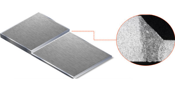
Automotive manufacturers rely on laser welded blanks (LWBs), which comprise metal sheets of different thicknesses and grades, to minimise and control the amount of material employed in different regions of a car, such as the frame and body (see Figure 1). Among other regulations, these blanks must keep up with crash safety requirements.

Figure 1. Top: A laser welded blank with a zoomed section showing the butt weld. Bottom: Examples of regions where LWBs may be used. Orange indicates components where properly designed LWBs can contribute to weight reduction, such as the B-pillar, side members, tunnel, and door rings.

Enter ArcelorMittal, a company that produces strong, high-quality steel. Through numerical simulation, they are optimising their welding process of LWBs to create blanks that ensure proper performance and minimise part weight by finding the best combination of different grades and thicknesses in their welded steel sheets.

Meeting Crash and Emission Requirements

“We optimise steel placement so that certain regions of a car are thinner and lighter but still strong enough, using advanced high-strength and press-hardened steels. Ultimately, we want excellent weld quality that meets safety requirements for crash tests,” remarks Dr. Sadok Gaied, who manages a team at ArcelorMittal working on numerical simulation of welding. For a weld to be considered safe, it cannot crack, break, or otherwise fail during a test.

ArcelorMittal uses laser welding to transform solid steel into molten metal by providing a concentrated heat source, allowing for narrow, deep welds (see Figure 2). “The high-power laser applies so much energy that some of the metal vaporises. When the steel melts, its density suddenly decreases and volume and material movement increase, generating a very high-pressure vapor. This creates a ‘keyhole,’ a narrow hole at the point of laser impact,” Gaied explains. “Then the surrounding steel melts, forming a molten pool. When that cools, it creates a connection between the two sheets of metal.”

Figure 2. Keyhole creation and the molten steel pool during laser welding. The keyhole migrates as the laser moves along the seam between two sheets, with molten steel filling in the space around and behind it as it travels.

“Most mechanical failures originate from defects in joining, because the joint is where different materials are connected. If the joint is done improperly, you can end up with stresses that are too high.” Welding with inappropriate parameters can also create instabilities that result in porosity in the weld, partial penetration, or undercutting, which results in a weaker connection. Examples of different weld defects are shown in Figure 3.

Figure 3. Left: Undercut geometry in the form of grooves at the top and bottom of the weld, caused by the ejection of molten steel. Center: A hole due to inappropriate collapse of the molten metal. Right: Bubbly weld due to complex hydrodynamic behaviour.

“To predict defects for different welding situations, we use numerical simulation that allows us to investigate the effects of changes in parameters like the laser power level,” Gaied continues. “In this way we can virtually test how operating conditions affect the likelihood of defects, as well as predict the fluid dynamics, thermal behaviour, and final shape of the weld.”

Understanding How Operating Conditions Impact Weld Quality

With the number of factors influencing the quality of a weld, the devil’s in the details: laser power, material reflection off the laser beam, welding speed, and wavelength affect behaviour around the keyhole such as heat transfer, phase change, and fluid flow. In particular, the keyhole angle and shape of the molten pool influence fluid flow behaviour resulting from the phase change and thermal loading.

“Fluid, thermal, and electrical behaviour are all intertwined here,” Gaied says. “It’s very important to know what’s happening in the weld in order to prevent defects. We needed to study all the physics together in order to track the fluid flow in and around the keyhole and understand its effect on the weld stability.”

Gaied’s team collaborated with Mickael Courtois, Muriel Carin, and Philippe Le Masson from Université Bretagne Sud and used COMSOL Multiphysics® software to analyse the temperature distribution in the molten and solid steel, the angle of the keyhole, and the fluid flow field as they change throughout the welding process. They included several studies in one COMSOL® simulation, beginning with an electromagnetic model that determined reflection and material absorption properties based on the angle of the laser’s reflection (see Figure 4).

Figure 4. COMSOL simulation of the laser reflection. Results show the electric field norm for different angles of reflection, resulting in different amounts of energy absorbed [1].

They also tested changing the power level, wavelength, and welding speed in order to predict the keyhole shape for different operating conditions. This model described the heat transfer and phase change as the metal melted, allowing the team to analyse the resulting vaporisation, fluid dynamics of the liquid-vapor interface, and the growth of the molten pool (see Figure 5).

Figure 5. Top left: Temperature field in the molten steel flowing around the keyhole. Bottom left: Results showing capillary inclination (keyhole angle) for different welding speeds, the temperature field in the surrounding metal, and the fluid flow field in the molten pool and the keyhole (arrow plots). Right: Three-dimensional view of the fluid flow directly around the keyhole during its formation [1].

Modelling Coupled Behaviour Sheds Light on Final Weld Results

To predict the final shape of the joint, Gaied’s team and the team from Université Bretagne Sud then modeled the penetration depth of the weld as a function of welding speed, laser power, and the size of the keyhole, based on results from their earlier study.

Full penetration into the sheets is required for a high-quality weld; partial penetration can occur when energy density is limited, at low power or high speed. Partial penetration can cause undercuts, resulting in a gap remaining between the two blanks (see Figure 6).

Figure 6. Top: Penetration depth for welding speeds of 6 m/minute (left) and 8 m/minute (right) with a 4kW laser. The slower case acheives full penetration, indicating sufficient energy density in the deposition. The faster case only results in partial penetration, indicating that there was not enough energy to create a high-quality connection. COMSOL results show the pentration depth and shape of the weld defect (yellow curve).

Perfected Welding Techniques for Safety and Emission Reduction

Offering the right LWBs to their customers – with the appropriate steel grade and sheet thicknesses to accommodate crash test specifications, weight requirements, and cost – requires choosing the right combination of welding parameters. Based on their simulations, Gaied’s team helps to determine a range of operating conditions for defect-free joints.

“Being able to understand these interacting physical phenomena and run a simulation that combined them all, rather than running multiple studies in parallel, was of huge benefit to us,” Gaied concludes. “We’re helping the automotive industry decreasing car weight, and making sure that our welds that they are of high quality and safe for drivers.”

References

1. M. Courtois, M. Carin, P. Le Masson, S. Gaied, M. Balabane

Guidelines in the experimental validation of a 3D heat and fluid flow model of keyhole laser welding. Journal of Physics D: Applied Physics (2016), 49 (15)

2. M. Courtois, M. Carin, P. Le Masson, S. Gaied, M. Balabane

A new approach to compute multi-reflections of laser beam in a keyhole for heat transfer and fluid flow modeling in laser welding. Journal of Physics D: Applied Physics (2013), 46 (50)