
Richard Anslow, System Applications Engineer and Neil Quinn, Product Applications Engineer, both with Analog Devices.
At the base of Industry 4.0 is reliable communications infrastructure. This infrastructure enables decision makers to extract data from machines, fielddevices, and factories. Ensuring reliability in robotics and human machine interfaces requires a good understanding of the underlying technology options.
While a factory floor and a medical operating theatre share little in common, the equipment used in both areas must deliver trusted and precise operation, which is often mission critical. With the need for smarter systems, more data, and higher fidelity, bandwidth requirements are increasing. At the same time, faster communication interfaces must deliver the same reliability and safety against environmental hazards and electromagneticcompatibility (EMC). EMC is the ability of systems to function as intended in their operating environment, without generating or being unduly affected by electrical noise.
Robotics and Machine Vision
Vision guided robots offer increased flexibility and higher production reliability in high value manufacturing environments. Without vision guidance, a robot would only be capable of repeating the same task until it’s reprogrammed. With machine vision, a robot can perform more intelligent tasks - for example, in a production line, a conveyor belt can be scanned for defective products, with the robot adjusting to pick up defective parts, as shown in Figure 1. In a hazardous EMC environment such as factory automation, the reliability and effectiveness of the vision/robot interface is dependent on the chosen wired link technology. There are several ways to implement the machine vision camera interface, including USB 2.0, USB 3.0, Camera Link, or gigabit Ethernet.
Table 1 compares the USB, Ethernet, and Camera Link standards using several key metrics. Industrial Ethernet offers many advantages, with the longest cable reach at up to 100 meters for 2-pair 100BASE-TX and 4-pair 1000BASE-T1,and up to 1km with the new 10BASE-T1L standard on a single twisted pair cable with high EMC performance. Cable reach using USB 2.0 or USB 3.0 is limited to 5 meters or less, unless specialised active USB cables are used, and EMC performance needs to be boosted using protection diodes and filtering. However, USB port ubiquity on industrialcontrollers and bandwidth up to 5Gbps provide the designer with some advantages.
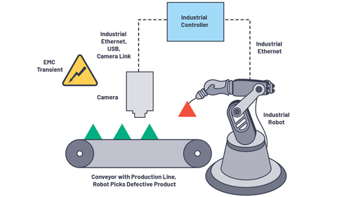
Figure 1. Camera machine vision and robotics, with Ethernet, USB, or Camera Link interface.
Camera Link requires dedicated frame grabber hardware on the industrial controller. USB or Ethernet do not require an additional frame grabber card in the industrial controller. Camera Link as a standard was first introduced in late 2000 and was the most commonly used interface for machine vision systems. USB- and Ethernet-based machine vision cameras are more widely used today, but Camera Link and frame grabbers are still used forapplications that require pre-processing for multiple cameras to reduce the main CPU load. Compared to gigabit Ethernet, even at base speed the Camera Link standard pushes twice as much data out, albeit over a shorter distance. The Camera Link physical layer is low voltage differential signalling (LVDS) based, with inherent EMC robustness due to common-mode noise coupling to each wire effectively cancelled out at the receiver. EMCrobustness on the LVDS physical layer can be boosted using magnetic isolation.
Time synchronisation between the industrial camera and the robot action can best be achieved using Ethernet on both camera and robot links, and an industrial controller that uses an IEEE 802.1 time sensitive network (TSN) switch. TSN defines the first IEEE standard for time-controlled data routing in switched Ethernet networks. Analog Devices offers a complete suite of Ethernet technologies, including physical layer transceivers and TSN switches, as well as system-level solutions, software, and security capabilities.
Table 1. Communication Interface Standard for Machine Vision Camera
|
Parameter |
USB 2.0 |
USB 3.0 |
Industrial Ethernet |
Camera Link |
|
Bandwidth |
1.5Mbps (low speed) |
Gbps (SuperSpeed) |
10Mbps, 100Mbps, |
2.04Gbps (base) 4.08Gbps (full) 6.8Gbps (deca) |
|
Cable Length |
5m |
3m |
10Mbps up to 1km, 100Mbps/1Gbps up to 100m |
10m |
|
Power andData on One Cable? |
Yes |
Yes |
Yes, power over Ethernet(PoE) or power over datalines (PoDL) |
Yes |
|
Frame GrabberRequired? |
No |
No |
No |
Yes |
|
Cable Costs |
Low |
Low |
Low |
High |
|
EMC Performance |
Low, requires EMC protection, filters, andsignal/power isolation |
Low, requires EMC protection, filters, andsignal/power isolation |
High (transformer magnetics are part of theEthernet specification) |
Medium (LVDS), requiressignal/power isolation for best performance |
Human Machine Interface (HMI)
A human machine interface (HMI) is commonly used to display data from a programmable logic controller (PLC) in a human readable visualrepresentation. A standard HMI can be used to track production time, while monitoring key performance indicators (KPI) and machine output. An operator can use the HMI for a variety of tasks, including turning off or on switches, and increasing or reducing the pressure or speed of a process. HMIs with integrated display screens are common; however, HMIs with external display options offer some advantages. HMI units with external High-Definition Multimedia Interface (HDMI®) ports are smaller and can be easily placed on control racks using standard DIN rails, which are also used to mount the monitored PLC.
Cable lengths of up to 15 meters are possible with HDMI, allowing easy routing to touch screen monitors and control rooms, as shown in Figure 2. Extending HDMI over longer cable lengths in industrial environments can be challenging, with EMC hazards affecting cabling. With motors and pumpsconnected to the DIN rail-mounted PLC, there is also a possibility of indirect transient overvoltages on the HMI.
Ensuring system robustness requires careful selection of interface technologies. Field bus technologies, such as CAN or RS-485, are common, withIndustrial Ethernet growing rapidly. Industry sources quote more than 61 million RS-485 (PROFIBUS®) nodes installed worldwide, with PROFIBUS process automation (PA) growing 7% year on year. The PROFINET (an Industrial Ethernet implementation) install base is at 26 million nodes,with 5.1 million devices installed in 2018 alone.1 As previously mentioned, high EMC performance can be achieved with Ethernet-based technologies as magnetics are written into the IEEE 802.3 Ethernet standard, and must be used at every node. RS-485 devices can include magnetic isolation to increase noise immunity, and protection diodes can be integrated on-chip, or placed on the communication PCB to increase robustness toelectrostatic discharges and transient overvoltages.
The HMI is commonly protected against electrostatic discharges, and signal robustness is boosted using ESD protection diodes. For the industrial HMI, integrated reinforced isolation can protect operators from electrical hazards. While reasonable isolation solutions are available for Ethernet andRS-485, video links are today isolated using costly fibre optics capable of gigabit transmission speeds. Analog Devices’ recent advances in magnetic isolation technology - such as the ADN4654/ADN4655/ADN4656 family, which is capable of data rates in excess of 1Gbps - provide the designer with acompelling and lower cost alternative.
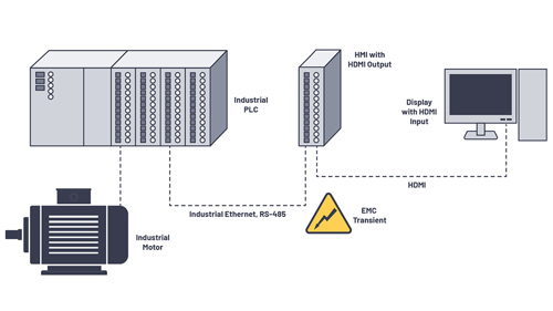
Figure 2. Human machine interface (HMI) with Ethernet and RS-485 inputs, and HDMI output.
Endoscopy
Surgical imaging, including endoscopy, is a unique application where the challenges of providing high fidelity images must be met while also ensuring the safety of the patient. Previous generation endoscopic devices, known as video endoscopes, use a series of glass lenses and a light conductor to allow the image to travel from the imaging head to the charge-coupled device (CCD) sensor. The use of visible light as a medium to carry the imagefrom the patient to the endoscope provides inherent isolation against harmful electrical currents but has significant drawbacks in manufacturing costs and image quality.2
Recent surgical imaging devices have moved to digital to overcome these challenges, switching from CCD to a CMOS sensor that can be easily scaled in size and embedded in the camera head. CMOS cameras eliminate the need for multiple lenses in series and improve overall image quality. The reduction in manufacturing cost makes single use surgical scopes a possibility, removing the challenges of sterilisation. The furtherminiaturisation of the camera head makes for less invasive surgery.3
With the move to digital endoscopes, a high speed electrical interface between the CMOS image sensor, which is in contact with the patient, and the camera control unit (CCU) is required. LVDS and scalable low voltage signalling (SLVS) have emerged as popular physical layers for this interconnect, offering high bandwidth and relatively low power.4 This interface, unlike in video endoscopes, is now electrical and has the potential toconduct hazardous currents. Without the inherent isolation of an optical medium, the system must be designed to separate the patient from any potentially harmful current flow.
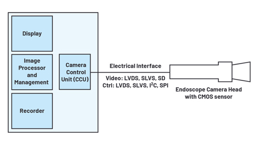
Figure 3. Electrical interfaces in a digital endoscope with CMOS image sensor.
In any medical system that is connected to the mains electrical supply, the safety of the patient is paramount. The IEC 60601 standard for medicalelectrical equipment sets out strict requirements for components that provide a means of patient protection (MOPP) against harmful voltages. Systemdesigners face a significant challenge when implementing high bandwidth solutions for transferring imaging data, while also meeting these stringentsafety requirements. The electrical video link from a CMOS image sensor to the endoscope CCU is one example where a safety-compliant, high speed connection is needed. Analog Devices offers unique solutions for implementing this high bandwidth link across a trusted safety barrier to meetthe requirements of the IEC 60601-1 standard.
Medical Displays
Other medical equipment, such as ventilators and electrocardiograms (ECGs), feature a direct connection to a patient for breathing assistance andmonitoring. Information regarding the patient is displayed to the operator on a graphical display, which is contained within the medical device itself. The display inside this piece of medical equipment is known, trusted, and certified for use as a medical device in accordance with the IEC 60101standard. The same cannot be guaranteed for any off-the-shelf external television sets and displays. To ensure patient safety, any external connections from the medical equipment to peripheral devices should also provide a barrier for patient protection. This isolation is trivial for legacy low speed interfaces such as RS-232, RS-485, and CAN, and can be achieved with standard digital isolators.
On the other hand, the isolation of a video port to an external display presents unique challenges. The bandwidth requirements for standardised interfaces to displays vastly exceed what can be realised using a reasonable amount of optocouplers or standard digital isolators. Further complexity is added when attempting to isolate the entire signal chain of the video interface. For example, the HDMI 1.3a protocol includes not only transition-minimised differential signalling (TMDS) for carrying video data, but also bidirectional control signals to exchange video/format information, power circuitry, and detect the connection and disconnection of display (sink) devices.5 These must all be considered when adding galvanic isolation, whichpresents a barrier for system designers. In many cases, it is not feasible using previous methods to add a safety isolation barrier to these displayports, so external display ports are not included in medical systems. Analog Devices provides a reference design for the galvanic isolation ofpopular video protocols, such as HDMI 1.3a, which allow for the drop-in additional safety protection in cases where patient protection is needed.
Gigabit Digital Isolation
The ADN4654 family of LVDS digital isolators is a new option for system designers where the combination of high bandwidth and trusted safety arerequired for video and camera applications. Featuring two channels of isolation with a data rate of up to 1.1Gbps per channel, these devices represent a significant leap in the speed capability of digital isolation. With a total throughput of 2.2Gbps in a 20-lead SSOP package, significant area savings can be achieved over solutions based on traditional digital isolators.
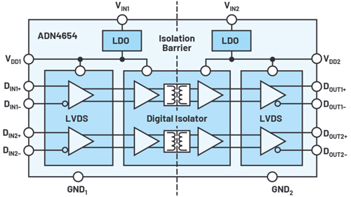
Figure 4. ADN4654 gigabit LVDS isolator block diagram.
To illustrate this, consider a video link transmitting 24-bit colour at 60Hz with a resolution of 1920×1080 (1080p). To transmit the required information across an isolation barrier, a total bandwidth of 4.4Gbps is needed. A typical optical fibre solution has sufficient bandwidth, but translation from copper medium to fibre optic requires a serialiser, a de-serialiser, and electrical-to-optical converters. A solution using standarddigital isolators will also require a serialiser, a de-serialiser, and over 30 channels of isolation, each running at 150Mbps. Both solutions presentoverhead to the system designer when adding isolation to a simple high bandwidth interface.
By leveraging the gigabit data rate of the ADN4654, the complexity of the system can be reduced, and this 4.4Gbps bandwidth can be achieved withusing just two devices. Each device has two channels, totalling four channels that operate at 1.1Gbps on each channel. The high channel bandwidthcan eliminate the need for any SERDES block in the signal chain. The space and complexity improvements are compounded in systems where morethan one video interface must be isolated.
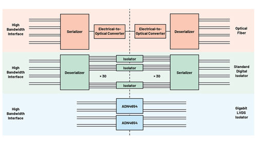
Figure 5. ADN4654-based system isolates high bandwidth interfaces with ease.
Physical layer interfaces that operate above 1Gbps have strict peak jitter and skew requirements to ensure reliable communication. Any component added into the signal chain, such as a digital isolator, must contribute minimal jitter and skew to avoid impacting system performance. Excessive jitter and skew can affect the sampling margin at the receiver and increase the overall bit error ratio. The ADN4654 features industry-leading skew performance of the 100ps max on a given channel, and 600ps part to part, which makes it well suited for isolating these high bandwidth interfaces.The ADN4654 adds minimal jitter, with a max random jitter performance of 4.8ps rms and max peak-to-peak deterministic jitter of 116ps using a PRBS-23 (pseudo random binary sequence) pattern. Pattern run lengths less than 23 bits are common, and jitter performance is improved beyond these values in protocols with encoding schemes with a lower run length, such as 8B/10B encoding.
The ADN4654/ADN4655/ADN4656 devices feature an internal LDO regulator for flexible power supply configurations and are available in variouschannel configurations. The ADN4654 is available in a 20-lead, wide-body SOIC package or a space-saving, 20-lead SSOP package. The SOICpackage features 5kV rms of isolation and 7.8mm of creepage and clearance, making these devices suitable for 1MOPP from 250V rms mains to the IEC 60601 standard. With potting to increase device creepage and clearance beyond 8mm, their use as a component in 2MOPP insulation systems is possible.
Isolating HDMI Using Circuit Note CN-0422
When faced with the task of adding safety isolation to a video interface, the complexity of the video protocol itself becomes a challenge. A solution toisolate each of the video, control, and power signals must be devised, and this presents a headache to equipment manufacturers. Drop-in reference design solutions reduce the system development time required to reach a functional design.
HDMI has become one of the de facto standards for commercial high definition televisions and displays since its release in late 2002. The widespread success of HDMI can be attributed to its feature set and reliable interoperability.
The EVAL-CN0422-EBZ reference design is available as a drop-in solution for users wishing to add galvanic isolation to existing HDMI 1.3a videoports. iCoupler® isolation technology is combined to transfer the necessary power and high speed video and control signals across an insulation barrier.
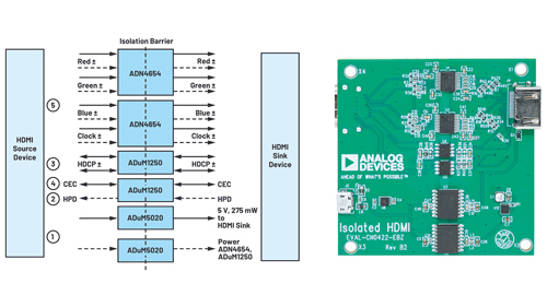
Figure 6. EVAL-CN0422-EBZ reference design for isolating the HDMI 1.3a protocol.
Video data in the HDMI 1.3a protocol is carried across four TMDS lanes: three data lanes and one clock lane. Each of these lanes must beindividually isolated. Traditional digital isolators support neither the high bandwidth nor the differential nature of TMDS, making them unsuitable. While TMDS differs slightly from LVDS, simple passive components can be used to allow compatibility with LVDS- compliant devices. These passive components are used in conjunction with two dual-channel gigabit ADN4654 isolated LVDS transceivers to isolate all four TMDS lanes. A pixel clock frequency of up to 110MHz is achievable, supporting 720p resolution at a frame rate of 60Hz.
HDMI protocol contains other low speed signals that are used for control purposes: the data display channel (DDC), consumer electronics control (CEC), and hot plug detect (HPD). The DDC is used to allow the source to read display EEID data from EEPROM and exchange relevantformatting information. The CEC signals allow for shared functionality between multiple connected source and sink devices. HPD is asserted bythe sink device when it has detected an attached source, signalling a connected device. These control signals are all isolated using two ADuM1250 devices, which provide bidirectional isolation of these signals where needed. Use of the ADuM1250 greatly simplifies the designchallenges associated with implementing a bidirectional isolation channel.
The reference design includes an isolated dc-to-dc power converter, the ADuM5020, which is used to power the display (sink) side of the isolateddevice. 275mW is also provided to the HDMI cable to support the sink devices, as required by the standard. The reference design is ready-made for isolating an HDMI source device, but the isolated power circuit can easily be adopted to isolate an HDMI sink device.
Industrial Ethernet
For machine vision applications, Analog Devices’ portfolio of multiprotocol Ethernet switches, Ethernet physical layer transceivers, as well as fullplatform solutions ensures seamless connectivity and operational efficiency.
Analog Devices’ fido5100/fido5200 REM switch family includes two, 2-port Industrial Ethernet embedded switches that interface to any processor,including any Arm® CPU, and ADI’s fido1100 communication controller.
These Industrial Ethernet embedded switches are designed so you can choose the type of processor that fits your application and not be forced touse a particular vendor’s protocol stack. REM attaches to the memory bus of a processor and looks like any other peripheral out on that bus. The memory cycle for REM goes down to 32ns (125Mbps with a 32-bit bus) to support the 12.5µs cycle time for EtherCAT and the 31.25μs cycle time forPROFINET IRT. Data is transferred to and from the switches using Priority Channel queues, so real-time data transfers can interrupt non-real-time data transfers without delay. These queues are managed by a switch driver and interface to the protocol stack to achieve the most efficient data transfers possible. This also means that application software doesn’t have to worry about managing the switch, setting low level registers, orkeeping track of intricate time management processes.
Another performance advantage of the Industrial Ethernet embedded switches is that their Priority Channel technology makes them immune to network loading effects. This advantage ensures that your application is up and running all the time, every time. The REM switches intelligentlyfilter packets to keep unwanted traffic from your processor, manage low priority traffic based on the loading of your processor, and guarantee the timely delivery of high priority packets, regardless of overall packet load.
Analog Devices’ ADIN1100, ADIN1200, and ADIN1300 Industrial Ethernet physical layer devices (PHYs) are designed for robustness in harshindustrial environments. Having completed extensive EMC and robustness testing, these products are ideally suited for applications demandingpredictable and secure communications. With industry-leading low latency and low power PHY technology, this portfolio supports data rates of 10Mbps, 100Mbps, and 1Gbps. Developed to maximise data transmission and signal integrity, they support multiple MAC interfaces while beinghoused in small packages. Designed to operate over extended industrial ambient temperature ranges, Industrial Ethernet PHYs provide the highest level of reliability for the Industrial Ethernet applications of today and tomorrow. ADIN1100 10BASE-T1L PHY provides 10Mbps Ethernet connectivity over a single twisted pair cable up to 1km and supports the hazardous areas use case (intrinsically safe Zone 0 applications)sometimes referred to as Ethernet-APL. ADIN1100 provides Ethernet connectivity to intrinsically safe certified devices including HMIs, industrial video cameras, and thermal cameras operating in hazardous areas.
What Does ADI Offer That Is Not Out There Already?
This article has described application requirements for safe and robust high bandwidth video or camera interfaces in industrial and medicalapplications and discussed key technology options for implementing these interfaces while maintaining critical performance. Analog Devices offersinnovative solutions, including:
- Industry’s first gigabit digital isolator family, ADN4654/ADN4655/ADN4656, which enables new options for isolating high bandwidth
- Industry’s first galvanically isolated video and camera ports, offering reduced cost and complexity compared to bulky fibre optic solutions.
- System compliance tested solutions, which reduce test and compliance One example is a reference design tested to the HDMIstandard.
- A complete suite of Industrial Ethernet products, including technologies, solutions, software, and security capabilities designed to connect the real world to factory networks and beyond to the cloud.
Conclusion
Analog Devices’ deep domain expertise and advanced technologies help partners connect the industrial devices and networks of the future. Theindustry’s first gigabit galvanic isolation technology provides alternative methods to isolate video and camera interfaces in diverse medical andindustrial applications. Analog Devices’ Ethernet solutions ensure that critical data is reliably delivered in harsh industrial applications, with TSN Ethernet switches and low latency, low power, long cable reach physical layer transceivers.
References
1 Bob. “PROFINET and PROFIBUS Node Count Tops 87 Million in 2018.” Profibus Group. May 16, 2019.
2 Danny Scheffer. “Endoscopes Use CMOS Image Sensors.” Vision Systems Design. July 30, 2007.
3 Ricardo A. Natalin and Jaime Landman. “Where Next for the Endoscope?” Medscape.
4 Dave Wilson. “Next-Generation Image Sensors.” NovusLight. November 28, 2016.
5 HDMI 1.3a specification.
About the Authors
Richard Anslow is a system applications engineer with the Connected Motion and Robotics Team within the Automation and Energy businessunit at Analog Devices. His areas of expertise are condition-based monitoring and industrial communication design. He received his B.Eng. andM.Eng. degrees from the University of Limerick, Limerick, Ireland. He can be reached at richard.anslow@analog.com.
Neil Quinn is a product applications engineer with Analog Devices working in the Interface and Isolation Technology Group in Limerick, Ireland. Neil received a bachelor’s degree in electronic engineering from the National University of Maynooth in 2013. He specialises in industrial and highspeed communication interfaces, such as RS-485 and LVDS, and ADI’s iCoupler digital isolation products. He can be reached at neil.quinn@analog.com.


UK Enters ‘Golden Age of Nuclear’
The delay (nearly 8 years) in getting approval for the Rolls-Royce SMR is most worrying. Signifies a torpid and expensive system that is quite onerous...