One of the key goals of the near-complete European COMET project is to develop robots that can compete against five-axis machine tools.
‘Up to now the problem with robots has been that they’re not quite accurate enough; they’re somewhere in the 2–5mm range,’ said Roland Krain of project partner TEKS. ‘If you calibrate it you can probably get down to a millimetre but it’s still not quite good enough for machining.’
The major current obstacles for fully automated machining are play, mechanical flexibility, thermal effects and particularly backlash.
‘A lot of companies have got robots that handle parts that need to be milled, but if they want to do milling they have to spend between £90,000 and £150,000 on a five-axis machine tool,’ Krain said. ‘If we can add a high-quality spindle into the mix, the robot is already there and so suddenly you’ve got a milling solution for a fraction of the cost — if we can get the accuracy of course.’
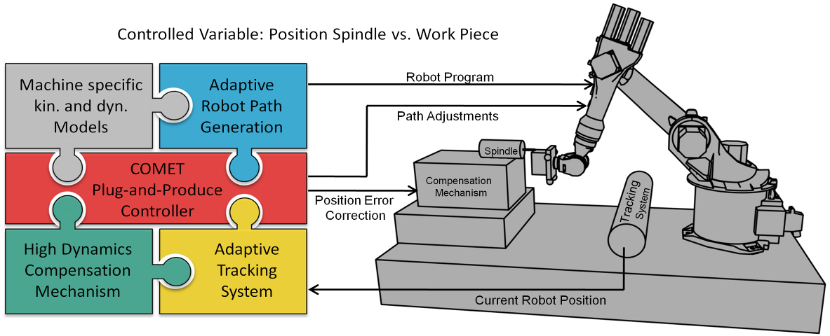
The cornerstone of this accuracy will be adaptive tracking, which is being developed in collaboration with COMET partner Nikon Metrology of Tamworth. It has devised a stepwise solution for increasing accuracy.
The first offline solution involves measuring the robot in more than 300 poses to determine where it deviates from where it should have been. That information is then fed back into the CAM software. When running, the software then compensates for backlash by driving the robot to what it thinks is the ‘wrong position’.
This can be complemented by an online, real-time system comprising three linear built-in charge coupled device (CCD) cameras with cylindrical lenses that measure the location of infrared LEDs mounted on the robot head. Essentially, it measures where the robot is, then checks where it should be and sends a compensation down to the robot controller in milliseconds.
Preliminary tests of these systems were performed last week in the UK demonstrating sub-1mm accuracy. The final phase of testing will be delivering case studies later this year such as machining the final leading edge of an aircraft wing and deburring parts on the turbine disk.
Meanwhile, TEKS is now exploring applications of COMET technology outside of industrial machining. One comes from the civil engineering sector for surveying quarries and mines using long-range laser scanning.
The new technology has proved difficult in that large amounts of rather unmanageable date are produced, which is difficult to visualise with existing computer hardware and software.
Using COMET technology, TEKS bypassed the computer to machine lightweight models of sites in polystyrene.
The main partners of the COMET project are BTU, Delcam, Nikon Metrology, Fraunhofer IPA, TEKS, SIR and AMRC Manufacturing.


IEA report claims batteries are ‘changing the game’
The weight and bulk of static batteries, even domestic units, is immaterial. The IEA's trilemma is illustrated here:-...